Original Industrial Spare Part
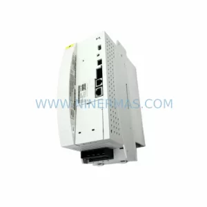
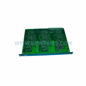
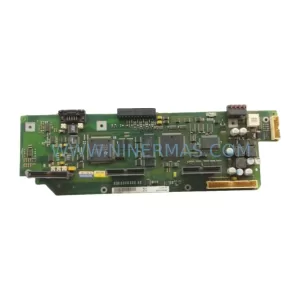
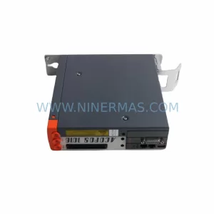
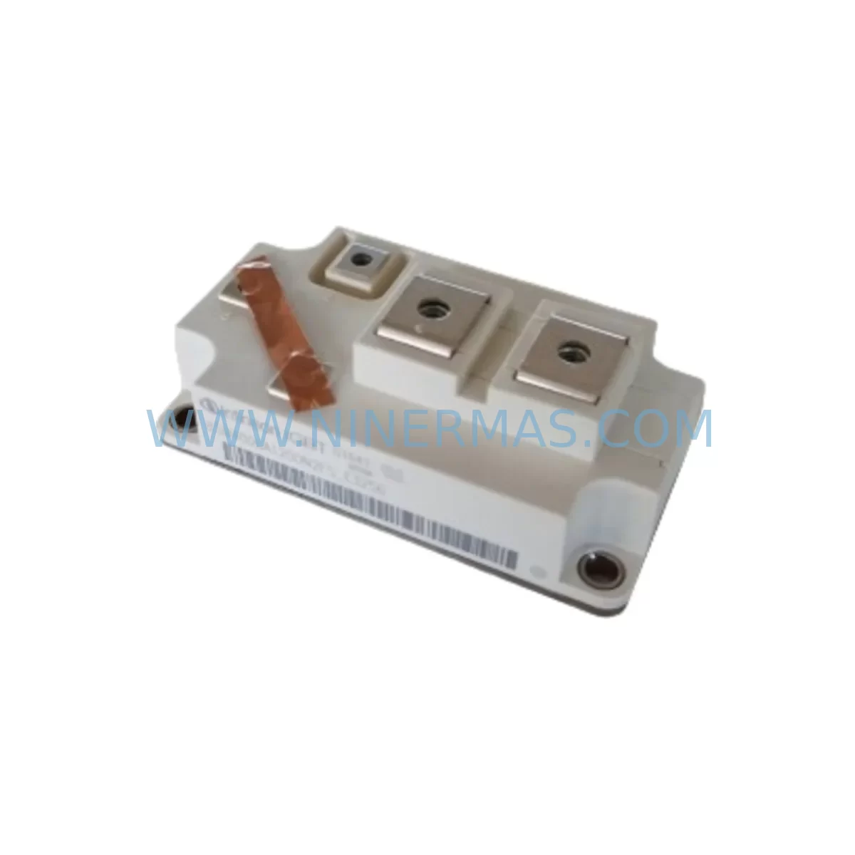
Bosch BSM400GA120DN2FSE3256 Service-Ready Spare Part
Verify the part, confirm the platform family, and move straight into quotation with the right commercial details.
RFQ Ready
- SKUBSM400GA120DN2FSE3256
- CategoryPLC & Industrial Automation Modules
- BrandBosch
- SupportAvailability, lead time, condition, and shipping coordination
How Buyers Usually Use This Page
- Confirm the exact part number and platform family before sending the quote request.
- Use direct email when quantity, condition, and destination are already defined internally.
- Switch to the broader brand or category archive when you need alternates nearby.
Series Navigation
Move through the most common platform families behind this part.
Product RFQ
Send this part directly for quotation.
Include quantity, required condition, destination country, and target delivery timing. Current reference: Bosch BSM400GA120DN2FSE3256 Service-Ready Spare Part with SKU BSM400GA120DN2FSE3256.
Bosch BSM400GA120DN2FSE3256 Service-Ready Spare Part: Spare Part Replacement & Downtime Risk Control
The Bosch BSM400GA120DN2FSE3256 is a high-current IGBT power module from the Bosch BSM Series, rated at 400 A / 1200 V, designed for demanding industrial drive, inverter, and power conversion applications. In critical manufacturing environments — including process lines, motor drive cabinets, and servo control systems — this module is a core switching component whose failure can trigger immediate production downtime. Maintaining a verified service-ready spare in your inventory is the most effective strategy to minimize mean time to repair (MTTR) and protect operational continuity.
At NINERMAS, every BSM400GA120DN2FSE3256 unit is sourced through controlled procurement channels, pre-shipment tested for gate threshold voltage, collector-emitter saturation voltage (VCEsat), and thermal resistance parameters before dispatch. Each unit ships with a 12-month warranty and full traceability documentation, giving maintenance engineers and procurement teams confidence in both quality and long-term supply availability.
Spare Maintenance Table
| Parameter | Specification |
|---|---|
| Part Number | BSM400GA120DN2FSE3256 |
| Brand / Manufacturer | Bosch (Infineon-heritage BSM Series) |
| Module Type | IGBT Power Module (Dual / Half-Bridge) |
| Collector Current (IC) | 400 A |
| Collector-Emitter Voltage (VCES) | 1200 V |
| Gate-Emitter Voltage (VGES) | ±20 V |
| Package / Footprint | BSM Series standard baseplate module |
| Thermal Interface | Baseplate-to-heatsink (thermal grease required) |
| Application Environment | Industrial drives, inverters, UPS, servo amplifiers |
| Compatibility | Direct replacement for BSM400GA120DN2 series variants |
| Mounting | Screw-mount baseplate; standard BSM footprint |
| Operating Temperature | -40°C to +150°C (Tj max) |
| Warranty | 12 Months — NINERMAS Quality Guarantee |
| Pre-Shipment Testing | VCEsat, IGBT gate threshold, leakage current, thermal resistance |
| Lead Time | In-stock: ships within 2–5 business days |
| Origin | Germany (DE) |
Maintenance Planning for Continuous Operation
When a BSM400GA120DN2FSE3256 module fails or is flagged during routine inspection, the replacement event is rarely isolated. Experienced maintenance engineers understand that an IGBT module failure in a drive cabinet is frequently accompanied by stress or damage to adjacent components in the same power stage or control loop. A disciplined site inspection should extend to the following areas before the replacement module is energized:
Gate Driver Boards: The gate driver circuit directly interfaces with the IGBT module’s gate-emitter terminals. Overvoltage transients that damage the IGBT often stress or destroy the gate driver output stage. Inspect and test the gate driver board — particularly the gate resistors, bootstrap capacitors, and optocoupler isolation stages — before commissioning the new module.
DC Bus Capacitor Banks: Electrolytic or film capacitors on the DC bus absorb switching ripple and protect the IGBT from voltage spikes. Capacitors that have aged, vented, or lost capacitance are a leading cause of IGBT re-failure after replacement. Measure ESR and capacitance on all DC bus capacitors during the same maintenance window.
Current Sensors and Hall-Effect Transducers: Phase current feedback is critical for drive protection. A faulty current sensor can cause the drive controller to misread load conditions, leading to overcurrent events that stress the new IGBT module. Verify sensor output accuracy and zero-offset calibration.
Thermal Management Components: The BSM400GA120DN2FSE3256 dissipates significant heat under full load. Inspect the heatsink surface for corrosion or warping, replace thermal interface material (TIM) with fresh high-conductivity paste, and verify that cooling fans or liquid cooling circuits are operating within specification. A blocked or degraded cooling path will shorten the service life of the replacement module.
Snubber Circuits and Clamp Diodes: Snubber capacitors and freewheeling diodes in the same inverter leg should be inspected for signs of thermal stress or dielectric breakdown. These components absorb energy during switching transitions and are exposed to the same fault conditions that caused the original module failure.
Control Power Supply (SMPS / 24 VDC Rail): The drive’s control board, encoder interface, and communication modules depend on a stable 24 VDC or 15 VDC auxiliary supply. A switching power supply that is marginal or noisy can cause erratic drive behavior and false fault trips after the IGBT is replaced. Measure output ripple and load regulation before returning the drive to service.
Encoder and Resolver Feedback Cables: Shielded encoder cables that run near high-current power cables are susceptible to EMI-induced noise. Inspect cable routing, shield termination, and connector integrity. A degraded feedback signal can cause speed loop instability that stresses the power stage.
I/O and Safety Relay Modules: Safety relays, STO (Safe Torque Off) circuits, and digital I/O modules in the same control cabinet should be functionally tested after any power stage replacement to confirm that protective interlocks are operating correctly and that no wiring disturbance occurred during the maintenance procedure.
Stocking the BSM400GA120DN2FSE3256 alongside these associated components — gate driver boards, DC bus capacitors, thermal interface materials, and control power supplies — as part of a structured spare parts kit significantly reduces the risk of extended downtime during an unplanned failure event.
Site Replacement Workflow
Step 1 — Isolation and Lockout/Tagout (LOTO): De-energize the drive cabinet, discharge the DC bus capacitors to below 50 VDC (verify with a calibrated meter), and apply LOTO before opening the power stage enclosure.
Step 2 — Document Existing Configuration: Photograph wiring, record gate driver board part numbers, and note torque values for bus bar connections before disassembly. This documentation accelerates reassembly and supports future maintenance records.
Step 3 — Remove the Faulty Module: Loosen bus bar connections in the correct sequence to avoid mechanical stress on the module terminals. Remove mounting screws from the baseplate. Lift the module clear of the heatsink and inspect the heatsink surface for contamination or damage.
Step 4 — Prepare the Heatsink: Clean the heatsink contact surface with isopropyl alcohol. Apply a uniform, thin layer of high-conductivity thermal interface material to the baseplate of the new BSM400GA120DN2FSE3256 module.
Step 5 — Install and Torque: Position the new module, insert mounting screws, and torque to the manufacturer’s specification (typically 3–5 Nm for BSM Series baseplate modules). Reconnect bus bars and gate driver connectors, verifying correct phase assignment.
Step 6 — Pre-Energization Checks: Verify gate driver supply voltages, confirm DC bus capacitor charge circuit is functional, and check all protective relay and STO circuit continuity before applying main power.
Step 7 — Commissioning and Load Test: Energize the drive at reduced load, monitor output current waveforms and heatsink temperature, and confirm stable operation before returning the system to full production load.
Spare Parts Support FAQ
Q1: Is the BSM400GA120DN2FSE3256 a direct drop-in replacement for earlier BSM400GA120DN2 variants?
Yes. The FSE3256 suffix designates a production revision within the BSM400GA120DN2 family. The electrical ratings, footprint, and terminal layout are compatible with earlier production variants. Always verify gate driver compatibility and confirm that the gate resistor values on the driver board are appropriate for the specific switching frequency of your application before commissioning.
Q2: How does NINERMAS verify the quality of BSM400GA120DN2FSE3256 units before shipment?
Every unit undergoes pre-shipment electrical testing covering collector-emitter saturation voltage (VCEsat), gate threshold voltage (VGEth), leakage current (ICES), and visual inspection for package integrity. Test records are available upon request. All units are covered by a 12-month warranty from the date of shipment.
Q3: Can NINERMAS support long-term or scheduled spare parts supply for the BSM Series?
Yes. NINERMAS offers long-term supply agreements for critical spare parts including the BSM400GA120DN2FSE3256 and related BSM Series modules. Scheduled procurement programs allow maintenance teams to maintain buffer stock without capital exposure, with agreed lead times and pricing stability. Contact our team to discuss a tailored spare parts program for your facility.
Q4: What information should I provide when ordering to confirm compatibility?
To confirm compatibility, provide the full part number (BSM400GA120DN2FSE3256), the drive or inverter model in which the module is installed, and if available, the gate driver board part number. Our technical team will cross-reference your application data and confirm suitability before shipment, eliminating procurement risk for critical replacement orders.
| Product Series | Other series |
|---|
Catalog Continuation
More Bosch modules in the catalog.
Use the brand lane to compare nearby part numbers, platform-adjacent modules, and other inquiry-ready listings before sending your final RFQ.
Catalog Continuation
Alternative parts within PLC & Industrial Automation Modules.
Stay inside the same system family when you need substitutes, adjacent modules, or a broader shortlist for procurement review.