Original Industrial Spare Part
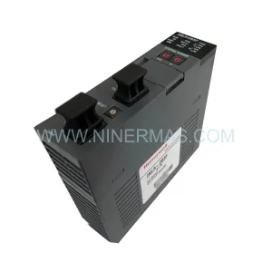
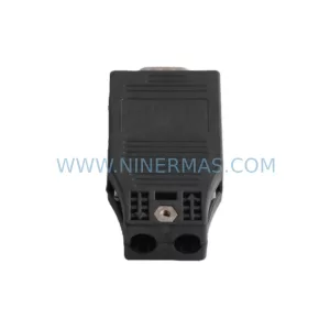
Siemens 6SE7090-0XX84-6FF5 Retrofit Drive Safety Module
Verify the part, confirm the platform family, and move straight into quotation with the right commercial details.
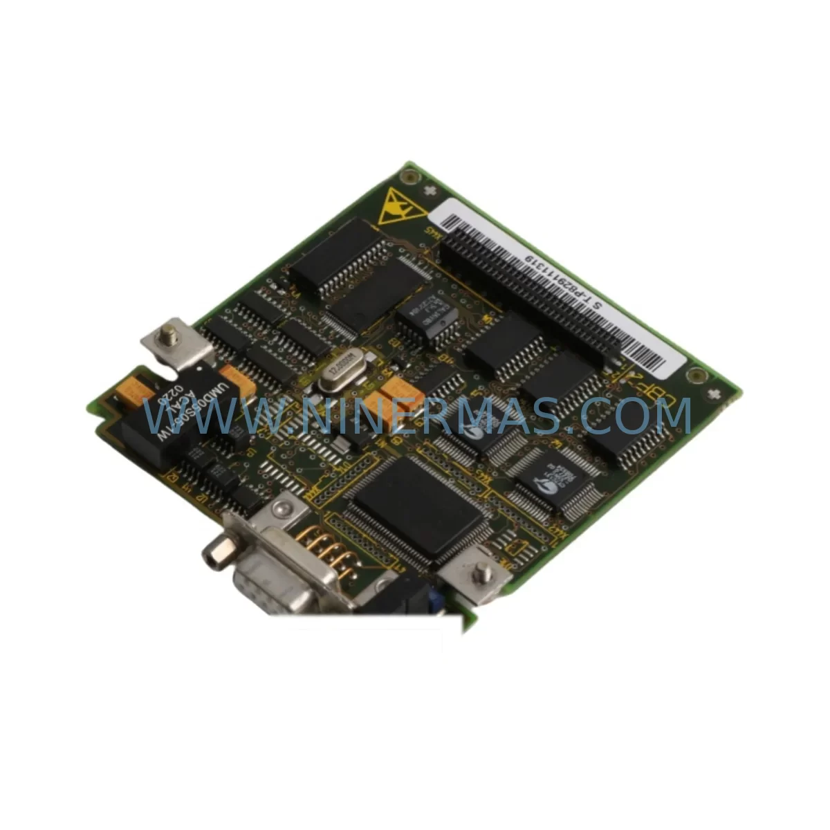
RFQ Ready
- SKU6SE7090-0XX84-6FF5
- CategorySIS Safety & Redundancy Systems
- BrandSiemens
- SupportAvailability, lead time, condition, and shipping coordination
How Buyers Usually Use This Page
- Confirm the exact part number and platform family before sending the quote request.
- Use direct email when quantity, condition, and destination are already defined internally.
- Switch to the broader brand or category archive when you need alternates nearby.
Series Navigation
Move through the most common platform families behind this part.
Product RFQ
Send this part directly for quotation.
Include quantity, required condition, destination country, and target delivery timing. Current reference: Siemens 6SE7090-0XX84-6FF5 Retrofit Drive Safety Module with SKU 6SE7090-0XX84-6FF5.
Siemens 6SE7090-0XX84-6FF5 Retrofit-Compatible Drive Safety Module for Legacy MASTERDRIVES Systems
The Siemens 6SE7090-0XX84-6FF5 is a ruggedized drive safety module designed for the SIMOVERT MASTERDRIVES 6SE70 platform — one of Siemens’ most widely deployed variable-speed drive families in heavy industrial environments. As the 6SE70 series approaches and exceeds its official end-of-life support window, procurement teams and automation engineers across manufacturing, mining, metals, and process industries are actively sourcing verified replacement units to extend operational continuity without committing to a full drive system overhaul.
At NINERMAS, we maintain dedicated stock of the 6SE7090-0XX84-6FF5 to support retrofit projects, emergency replacements, and planned lifecycle extensions. Every unit ships with a 12-month warranty and passes pre-shipment functional verification before dispatch.
Upgrade Compatibility Table
| Parameter | Details |
|---|---|
| SKU / Part Number | 6SE7090-0XX84-6FF5 |
| Brand / Series | Siemens SIMOVERT MASTERDRIVES (6SE70) |
| Module Function | Ruggedized Drive Safety Module — Safe Stop, STO-compatible logic interface |
| Mounting / Installation | Slot-in module for 6SE70 drive chassis; confirm rack slot assignment before installation |
| Communication Interface | Compatible with PROFIBUS DP, USS protocol; verify CBP2 or CBD communication board presence |
| Replacement Compatibility | Direct replacement within 6SE70 chassis; verify firmware revision on CU (Control Unit) board |
| Terminal Wiring | Confirm 24 VDC control supply, STO input wiring, and enable signal terminals against existing drawings |
| Commissioning Notes | Parameter backup via DriveMonitor or STARTER recommended before swap; re-download after replacement |
| Warranty | 12 Months — covers manufacturing defects and functional failure under normal operating conditions |
| Stock Status | Available — contact sale@ninermas.com for lead time and quantity confirmation |
Retrofit Planning for Existing Automation Systems
Replacing the 6SE7090-0XX84-6FF5 within a live production environment requires careful pre-planning across multiple system layers. The 6SE70 drive platform is typically integrated into control cabinets alongside a range of companion components, and a successful retrofit depends on verifying compatibility at each interface point.
Begin by auditing the existing 6SE70 Control Unit (CU) — commonly the 6SE7090-0XX84-0FA0 or similar CU board variant — to confirm firmware version compatibility with the replacement safety module. The CU communicates with the safety module over the internal drive bus, and mismatched firmware revisions can prevent proper STO (Safe Torque Off) handshaking. If the CU board is also aged or showing intermittent faults, sourcing a matched CU replacement simultaneously reduces the risk of a second unplanned outage.
Next, inspect the Power Unit (Inverter section) of the 6SE70 chassis. In many retrofit scenarios, the power section remains serviceable while the control and safety modules have degraded. Confirm that the DC bus voltage, IGBT gate driver signals, and thermal management components are within specification before isolating the safety module as the sole fault source. Companion power supply modules such as the 6EP1333-3BA00 SITOP PSU or equivalent 24 VDC panel supply should be verified for output stability, as safety module logic circuits are sensitive to supply ripple.
For sites running PROFIBUS DP networks, verify that the CBP2 communication board (e.g., 6SE7090-0XX84-0KF0) is seated correctly and that the PROFIBUS address is documented before removal. After module replacement, the drive must be re-addressed and the GSD file re-imported into the SIMATIC S7 project if the DP master is a SIMATIC S7-300 or S7-400 CPU. Confirm that the PLC program’s drive fault handling and STO acknowledgment logic remains intact — particularly if the safety circuit interfaces with a SIRIUS 3SK1 safety relay or a F-CPU failsafe controller.
Terminal wiring adaptation is a common challenge in 6SE70 retrofits. The STO input terminals, enable inputs, and analog reference signal terminals (0–10 V or 4–20 mA) must be mapped against the original wiring diagram. Where original drawings are unavailable, the terminal layout of the 6SE7090-0XX84-6FF5 should be cross-referenced against the MASTERDRIVES Compact PLUS or Vector Control documentation. Pay particular attention to the 24 VDC control supply polarity and the shielding continuity of analog signal cables to avoid noise-induced faults after commissioning.
In control cabinets where space is constrained, confirm the physical slot position of the safety module within the 6SE70 chassis. Some installations use 6SE70 expansion racks or auxiliary I/O modules such as the 6SE7090-0XX84-0JC0 terminal expansion board to extend the I/O capacity of the base drive. If the retrofit involves upgrading from a basic safety stop function to a more comprehensive safety package, additional slot space and a revised cabinet layout may be required.
HMI integration should also be reviewed. Sites using SIMATIC OP7, OP17, or TP270 operator panels connected via MPI or PROFIBUS will need to verify that drive status messages, fault codes, and parameter display screens remain functional after the module swap. In some cases, HMI screen tags referencing drive-specific data blocks may require re-mapping if the replacement module introduces revised parameter numbering.
Downtime Control During System Migration
Minimizing unplanned downtime is the primary operational concern when replacing a safety module in a running production system. A structured approach to the 6SE7090-0XX84-6FF5 replacement can reduce total outage time to a planned maintenance window of 2–4 hours in most standard installations.
Step 1 — Parameter Backup: Before any hardware is disturbed, connect a laptop running Siemens DriveMonitor or STARTER software to the drive’s USS or PROFIBUS interface and perform a full parameter upload. Save the parameter file (.par or .uds format) to a secure location. This backup is the single most important step — it allows the replacement module to be commissioned with the exact same speed references, ramp times, current limits, and safety function configurations as the original unit.
Step 2 — Controlled Shutdown: Coordinate with the production supervisor to bring the affected drive to a controlled stop. Use the drive’s built-in coast-stop or ramp-down function rather than an emergency stop, which can stress mechanical components. Isolate the drive from the AC supply using the upstream circuit breaker or contactor, and discharge the DC bus capacitors fully before opening the cabinet door — typically 5 minutes after power removal for standard 6SE70 chassis sizes.
Step 3 — Module Swap and Wiring Verification: Remove the faulty 6SE7090-0XX84-6FF5 module, photograph the terminal connections before disconnection, and install the replacement unit. Re-terminate all control wiring according to the original drawings or the photographs taken during removal. Verify STO input wiring continuity with a multimeter before re-energizing.
Step 4 — Parameter Restore and Functional Test: Power up the drive and download the saved parameter file. Perform a no-load functional test — jog the motor at low speed and verify that the STO function responds correctly to a test trip signal from the safety relay or F-CPU. Confirm that PROFIBUS communication is re-established and that the PLC program is receiving correct drive status feedback before returning the system to automatic mode.
By following this sequence, most sites can complete a 6SE7090-0XX84-6FF5 replacement within a single planned shift, preserving the original control logic, HMI displays, and safety interlock behavior without requiring a full system re-commissioning.
Retrofit Support FAQ
Q1: Is the 6SE7090-0XX84-6FF5 a direct drop-in replacement for the original module in my 6SE70 drive?
In most cases, yes — the 6SE7090-0XX84-6FF5 is designed for slot-in installation within the standard 6SE70 chassis. However, you should verify the firmware revision of your existing Control Unit board and confirm that the safety module variant matches your drive’s hardware configuration (Compact PLUS, Vector Control, or Servo Control). Contact our technical team with your full drive nameplate data for a pre-sale compatibility check.
Q2: What commissioning steps are required after installing the replacement module?
After physical installation, a parameter download from a previously saved backup file is strongly recommended. If no backup exists, the drive will need to be re-parameterized from scratch using the original application data. Key parameters to verify include the STO enable logic, ramp-up/ramp-down times, current limits, and PROFIBUS node address. A no-load test run should be completed before returning the drive to full production load.
Q3: Can you supply the 6SE7090-0XX84-6FF5 for emergency same-week dispatch?
Yes. NINERMAS maintains stock of the 6SE7090-0XX84-6FF5 for urgent retrofit and breakdown scenarios. Contact us at sale@ninermas.com or call +0086 187 5021 5667 to confirm current availability and arrange expedited shipping. We serve customers across Asia, Europe, and North America with DHL Express and freight forwarding options.
Q4: What does the 12-month warranty cover?
All units supplied by NINERMAS carry a 12-month warranty from the date of shipment. The warranty covers manufacturing defects and functional failure under normal operating conditions as specified in the Siemens MASTERDRIVES technical documentation. Units that have been subjected to incorrect installation, overvoltage events, or physical damage are excluded. Our team provides pre-shipment functional testing on all safety modules before dispatch to minimize the risk of DOA (dead-on-arrival) units reaching your site.
| Product Series | MASTERDRIVES |
|---|---|
| Country of Origin | DE |
Catalog Continuation
More Siemens modules in the catalog.
Use the brand lane to compare nearby part numbers, platform-adjacent modules, and other inquiry-ready listings before sending your final RFQ.
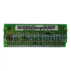
SKU: 6SE7038-6EK84-1BH0
Siemens 6SE7038-6EK84-1BH0 Retrofit Drive Control Module
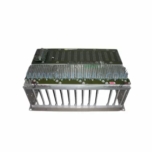
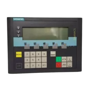
SKU: 6SL3055-0AA00-4CA5
Siemens 6SL3055-0AA00-4CA5 Retrofit-Compatible Operator Panel for Legacy Systems
Catalog Continuation
Alternative parts within SIS Safety & Redundancy Systems.
Stay inside the same system family when you need substitutes, adjacent modules, or a broader shortlist for procurement review.