Original Industrial Spare Part
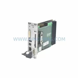
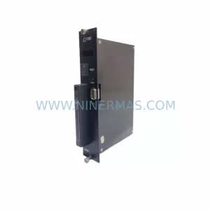
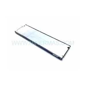
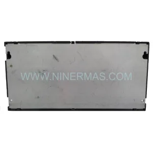
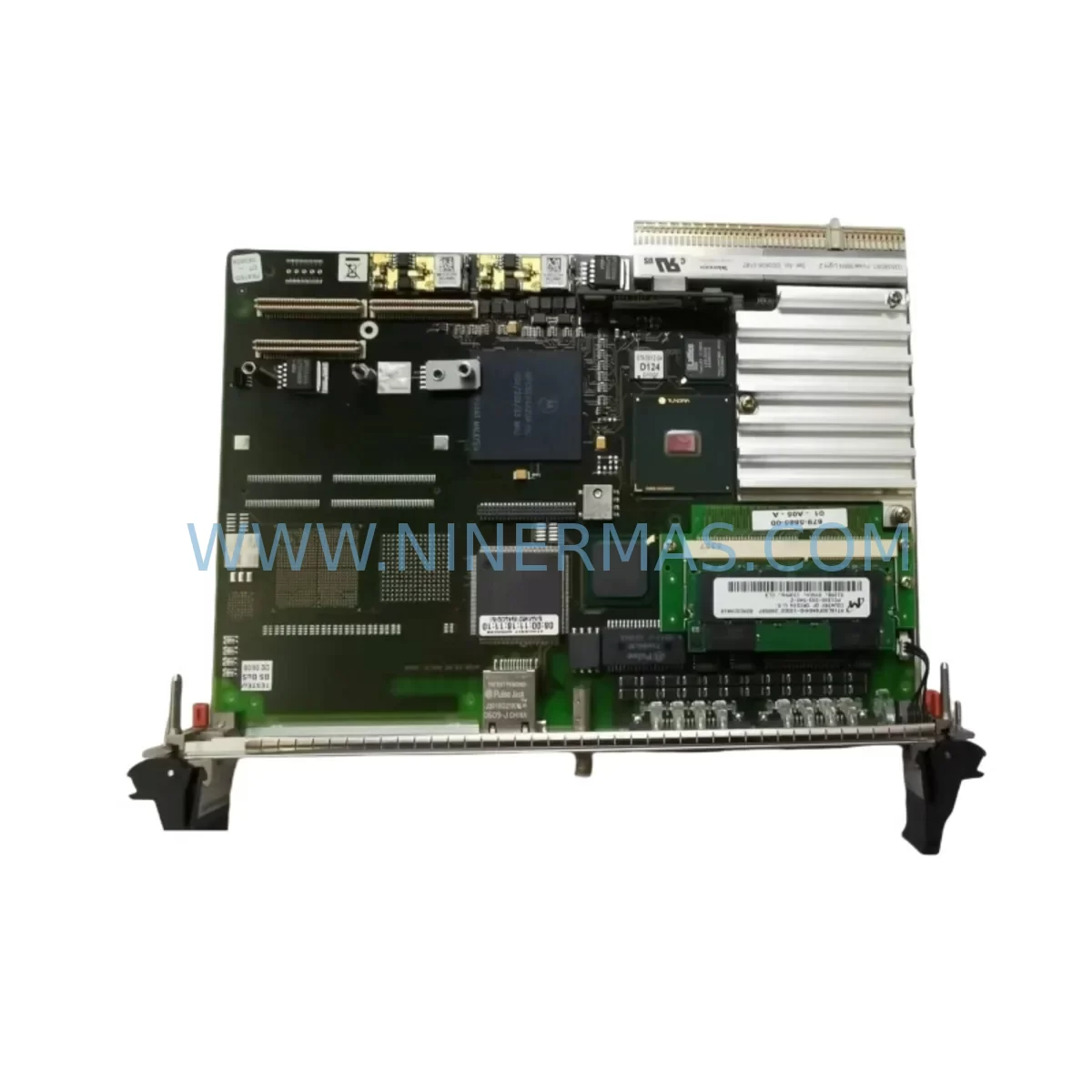
Tektronix G35SB080 671-5612-06 Retrofit-Compatible Control Board for Legacy Systems
Verify the part, confirm the platform family, and move straight into quotation with the right commercial details.
RFQ Ready
- SKUG35SB080 671-5612-06
- CategoryPLC & Industrial Automation Modules
- BrandTektronix
- SupportAvailability, lead time, condition, and shipping coordination
How Buyers Usually Use This Page
- Confirm the exact part number and platform family before sending the quote request.
- Use direct email when quantity, condition, and destination are already defined internally.
- Switch to the broader brand or category archive when you need alternates nearby.
Series Navigation
Move through the most common platform families behind this part.
Product RFQ
Send this part directly for quotation.
Include quantity, required condition, destination country, and target delivery timing. Current reference: Tektronix G35SB080 671-5612-06 Retrofit-Compatible Control Board for Legacy Systems with SKU G35SB080 671-5612-06.
Tektronix G35SB080 671-5612-06 Retrofit-Compatible Control Board for Legacy Systems
The Tektronix G35SB080 671-5612-06 is a retrofit-compatible industrial control board engineered to serve as a direct or near-direct replacement for legacy automation and instrumentation systems where the original board has reached end-of-life, been discontinued, or is no longer available through standard distribution channels. Sourced from verified supply chains and subjected to pre-shipment functional testing, this board supports system integrators, maintenance engineers, and procurement teams seeking to extend the operational life of existing control infrastructure without committing to a full platform migration.
Industrial facilities running legacy Tektronix-based control architectures face increasing pressure as original spare parts become scarce. The G35SB080 671-5612-06 addresses this challenge directly — providing a tested, warranted, and immediately deployable solution for control cabinet upgrades, panel retrofits, and system restoration projects. Whether you are managing a discrete manufacturing line, a process control loop, or a test and measurement rack, this board is designed to minimize engineering rework and reduce unplanned downtime during replacement.
Upgrade Compatibility Table
| Parameter | Details |
|---|---|
| SKU / Part Number | G35SB080 / 671-5612-06 |
| Brand | Tektronix |
| Product Type | Industrial Control Board |
| Form Factor | PCB module, rack or panel mount (verify chassis slot dimensions before installation) |
| Interface Compatibility | Compatible with legacy Tektronix backplane and connector pinouts; verify edge connector pitch and keying before insertion |
| Communication Protocol | Confirm GPIB, RS-232, or proprietary bus compatibility with host system firmware version |
| Power Requirements | Verify supply rail voltages (typically ±5V / ±12V / ±15V) against existing PSU capacity before installation |
| Installation Space | Confirm card slot clearance, adjacent module spacing, and airflow path in existing enclosure |
| Replacement Scope | Direct board swap for same-series legacy units; cross-series retrofit may require firmware or jumper reconfiguration |
| Commissioning Notes | Re-run self-test routines post-installation; verify calibration offsets and address settings match original configuration |
| Warranty | 12-Month Warranty — covers manufacturing defects and functional failure under normal operating conditions |
| Pre-Shipment Testing | Yes — functional verification completed before dispatch |
| Lead Time | Subject to stock availability; contact for committed delivery schedule |
Retrofit Planning for Existing Automation Systems
Successful retrofit of the Tektronix G35SB080 671-5612-06 into an existing control system requires a structured pre-installation review. Engineers should begin by auditing the host chassis or rack for available slot positions, verifying that the backplane connector layout matches the board’s edge connector configuration. In multi-board systems, adjacent modules such as I/O expansion cards, signal conditioning boards, and communication interface modules must be documented to ensure the replacement board does not conflict with address assignments or interrupt lines already in use.
Power supply capacity is a critical checkpoint. Legacy control cabinets often run power supply units at or near rated capacity, and adding a replacement board — even a like-for-like swap — warrants a load audit of the existing PSU. In systems where the original power supply is also aging, it is common practice to simultaneously replace or recondition the PSU alongside the control board to avoid cascading failures post-retrofit. Tektronix-compatible power supply modules and regulated DC distribution boards are frequently sourced as companion parts during this phase.
Terminal wiring and signal routing must be mapped before the old board is removed. Photograph or document all connector positions, wire labels, and terminal block assignments. In systems using analog signal inputs — such as 4–20 mA process loops or thermocouple inputs — signal isolators or barrier modules may be required to protect the new board from ground loops or transient spikes present in the existing field wiring. Signal isolation modules are a standard addition in brownfield retrofit projects and should be budgeted into the scope of work.
For systems that include HMI panels or operator workstations communicating with the control board via serial or proprietary protocols, the HMI screen configuration and tag database must be reviewed. If the replacement board uses a slightly different register map or communication timing, HMI screens may require tag remapping or driver updates. This is particularly relevant in systems where the HMI communicates via RS-232 or GPIB, as protocol timing parameters are often firmware-dependent. Programming cables and interface adapters compatible with the Tektronix platform should be on hand during commissioning.
In rack-based systems, the physical installation space must be confirmed. Measure the card slot depth, width, and height, and verify that the replacement board’s PCB dimensions fall within tolerance. In dense control cabinets, adjacent modules — including communication gateway cards, analog output modules, and discrete I/O boards — may need to be temporarily removed to allow safe board insertion and connector seating. After installation, all adjacent modules should be reseated and their status verified before powering the system.
Where the legacy system includes a programmable controller or embedded processor communicating with the G35SB080 671-5612-06, the program logic should be backed up before any hardware change. Ladder logic, function block diagrams, or structured text programs stored in the controller should be exported and archived. After the board swap, a controlled power-up sequence — starting with the control board alone before enabling field I/O — allows engineers to confirm the board initializes correctly before exposing it to live process signals.
Downtime Control During System Migration
Minimizing production downtime during a control board replacement is a primary concern for maintenance teams operating in continuous process or high-throughput discrete manufacturing environments. The recommended approach for the Tektronix G35SB080 671-5612-06 retrofit is to complete all pre-installation preparation — wiring documentation, program backup, address verification, and power audit — during normal production hours, reserving the actual board swap for a planned maintenance window.
Before the maintenance window opens, the replacement board should be bench-tested in a representative configuration if possible. This includes powering the board from a bench PSU at the correct voltage rails, confirming that the board initializes without fault codes, and verifying communication response on the relevant interface. Pre-shipment testing performed by the supplier provides a baseline, but site-level bench verification adds a further layer of confidence and can identify any configuration differences between the outgoing and incoming boards before the system is taken offline.
During the swap, the original board should be retained and stored — not discarded — until the replacement has been confirmed stable in production for a minimum observation period (typically 72 hours to two weeks depending on process criticality). This preserves the option to revert if an unexpected compatibility issue emerges. Original program logic, calibration data, and configuration files should be stored in a version-controlled archive accessible to the engineering team.
After installation, a structured commissioning sequence should be followed: power-up the control board, confirm self-test pass, verify communication link to the host controller or HMI, check all I/O channel assignments, and run a functional test against a known-good process condition before returning the system to automatic control. Documenting the commissioning steps and results creates a traceable record that supports future maintenance and audit requirements.
Retrofit Support FAQ
Q1: Is the Tektronix G35SB080 671-5612-06 a direct drop-in replacement for the original board?
In most same-series applications, yes — the board is designed for direct substitution. However, engineers should verify connector pinout, address jumper settings, and firmware compatibility before installation, as minor hardware revisions in the original platform may require configuration adjustments. Contact our technical team with your system’s serial number and firmware version for a pre-sale compatibility confirmation.
Q2: What pre-shipment testing is performed, and what does the 12-month warranty cover?
Every unit undergoes functional verification prior to dispatch, confirming power-on initialization, communication interface response, and basic I/O operation. The 12-month warranty covers manufacturing defects and functional failure under normal operating conditions. It does not cover damage resulting from incorrect installation, overvoltage, or physical mishandling. Warranty claims are supported with a documented returns and replacement process.
Q3: What should I verify regarding wiring and terminal connections before installation?
Document all existing connector positions, wire labels, and terminal assignments before removing the original board. Verify that the replacement board’s connector types and pinout match the existing harness. In systems with analog signal wiring, check for ground loop risk and consider adding signal isolation barriers if the field wiring runs are long or share conduit with power cables. Confirm that all terminal screws are torqued to specification after reconnection.
Q4: What is the typical lead time and stock availability?
Stock availability varies. We maintain inventory of high-demand legacy Tektronix spare parts and can confirm current stock levels upon inquiry. For projects requiring committed delivery schedules or volume procurement, contact our sales team at sale@ninermas.com or call +0086 187 5021 5667 to discuss a supply agreement with fixed lead times and reserved stock allocation.
| Product Series | Legacy |
|---|
Catalog Continuation
More Tektronix modules in the catalog.
Use the brand lane to compare nearby part numbers, platform-adjacent modules, and other inquiry-ready listings before sending your final RFQ.
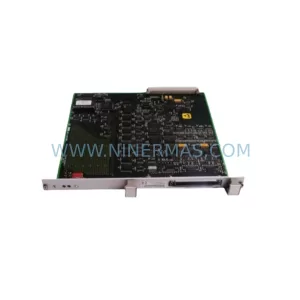
SKU: 7KK1200-2PE01 C73249-A97-L1-8
Tektronix 7KK1200-2PE01 C73249-A97-L1-8 Retrofit Control Module
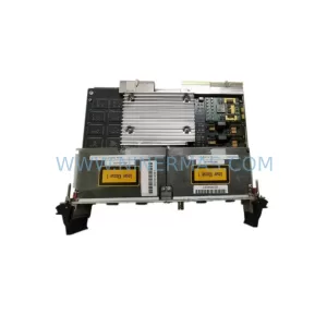
SKU: PCE-2 LIF-1 K15MB000 671-5532-02
Tektronix PCE-2 LIF-1 K15MB000 671-5532-02 Service-Ready Spare Part
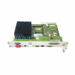
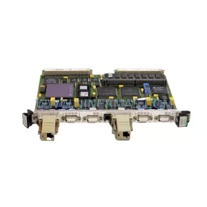
SKU: 7KK1297-2PT11 C7329-A97-L2-8
Tektronix 7KK1297-2PT11 C7329-A97-L2-8 Safety-Reliable E1 Sync Module
Catalog Continuation
Alternative parts within PLC & Industrial Automation Modules.
Stay inside the same system family when you need substitutes, adjacent modules, or a broader shortlist for procurement review.