Original Industrial Spare Part
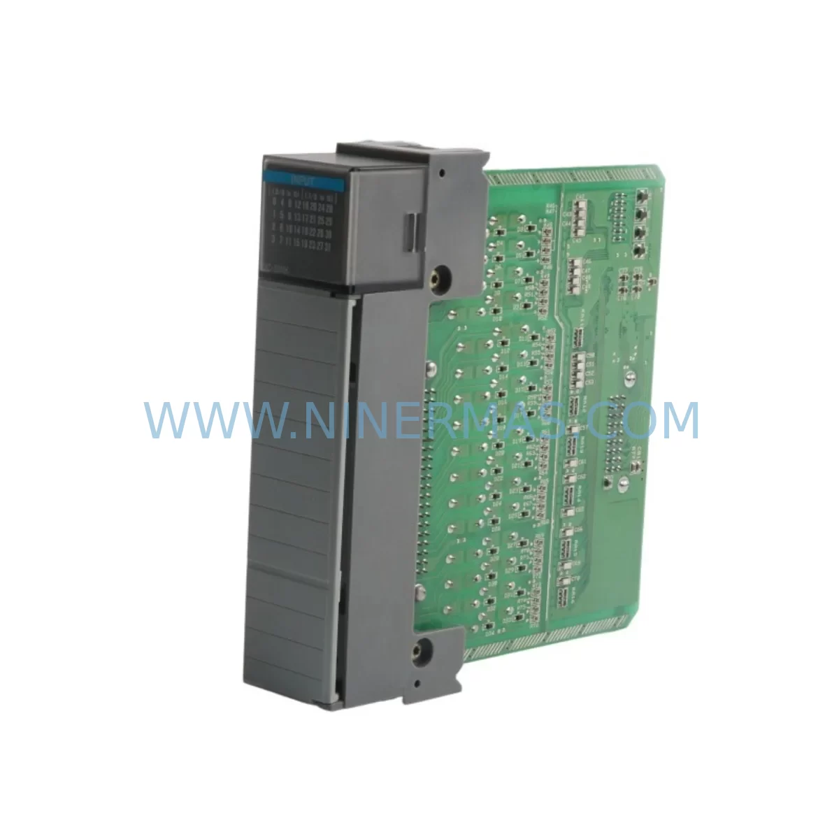
Allen-Bradley 1746-OG16 Retrofit-Compatible Output Module
Verify the part, confirm the platform family, and move straight into quotation with the right commercial details.
RFQ Ready
- SKU1746-OG1
- CategoryPLC & Industrial Automation Modules
- BrandAllen-Bradley
- SupportAvailability, lead time, condition, and shipping coordination
How Buyers Usually Use This Page
- Confirm the exact part number and platform family before sending the quote request.
- Use direct email when quantity, condition, and destination are already defined internally.
- Switch to the broader brand or category archive when you need alternates nearby.
Series Navigation
Move through the most common platform families behind this part.
Product RFQ
Send this part directly for quotation.
Include quantity, required condition, destination country, and target delivery timing. Current reference: Allen-Bradley 1746-OG16 Retrofit-Compatible Output Module with SKU 1746-OG1.
Allen-Bradley 1746-OG16 Retrofit-Compatible Output Module: Legacy System Compatibility & Smooth Upgrade
The Allen-Bradley 1746-OG16 is a 16-point DC output module designed for the SLC 500 modular chassis platform. As production lines age and original equipment manufacturers discontinue support for legacy control hardware, the 1746-OG16 remains one of the most sought-after replacement modules for engineers managing brownfield automation environments. Whether you are restoring a failed output card, expanding an existing SLC 500 rack, or executing a phased migration away from end-of-life hardware, this module provides a verified drop-in solution that minimizes engineering rework and unplanned downtime.
NINERMAS maintains tested inventory of the 1746-OG16 to support customers across manufacturing, utilities, material handling, and process industries who depend on continued availability of discontinued Allen-Bradley components. Every unit ships with a 12-month warranty and passes pre-shipment functional verification.
Upgrade Compatibility Table
| Parameter | 1746-OG16 Specification | Retrofit Notes |
|---|---|---|
| Output Type | DC Transistor (Sourcing) | Verify field device polarity before wiring |
| Number of Points | 16 Outputs | Confirm I/O address map in RSLogix 500 program |
| Output Voltage Range | 10–50V DC | Check field device voltage compatibility |
| Output Current per Point | 0.5A max | Verify load current does not exceed rating |
| Chassis Compatibility | 1746 SLC 500 Modular Chassis (4, 7, 10, 13-slot) | Compatible with 1746-A4, 1746-A7, 1746-A10, 1746-A13 |
| Backplane Interface | SLC 500 Backplane | No adapter required; direct slot insertion |
| Communication Protocol | SLC 500 Backplane Bus | Compatible with 1747-L20, 1747-L30, 1747-L40, 1747-L553 processors |
| Programming Software | RSLogix 500 / RSLogix Micro | No program changes required for direct replacement |
| Installation Space | Single SLC 500 Slot | Confirm slot availability in existing chassis |
| Wiring Termination | Removable Terminal Block (RTB) | Existing RTB can be transferred; verify terminal labeling |
| Warranty | 12-Month Warranty — All units tested prior to shipment | |
Retrofit Planning for Existing Automation Systems
Replacing a failed or aging 1746-OG16 in an active production environment requires careful pre-planning to avoid extended downtime and configuration errors. The following guidance covers the key engineering checkpoints that field technicians and automation engineers should address before and during the replacement process.
Power Budget Verification: Before inserting the replacement 1746-OG16, confirm that the SLC 500 chassis power supply — typically a 1746-P1, 1746-P2, or 1746-P4 — has sufficient remaining capacity to support the module’s backplane current draw. The 1746-OG16 draws 185mA from the 5V backplane bus. If the chassis is near its power budget limit due to other installed modules such as analog input cards (1746-NI4 or 1746-NI8), specialty communication modules, or high-density I/O cards, a power supply upgrade may be required before the output module can be safely added.
Terminal Block and Field Wiring: The 1746-OG16 uses a removable terminal block (RTB) that can be detached from the failed module and transferred directly to the replacement unit. This significantly reduces rewiring time. Before transfer, photograph or document the existing terminal assignments and verify that the RTB locking mechanism is undamaged. If the original RTB is corroded or damaged, a replacement RTB compatible with the 1746-OG16 should be sourced alongside the module.
Slot Address and I/O Configuration: In RSLogix 500, each module slot is assigned a specific I/O address. When replacing the 1746-OG16 in the same physical slot, the address mapping remains unchanged and no program modification is required. However, if the module is being relocated to a different slot — for example, due to chassis reconfiguration or the addition of a 1746-A13 expanded chassis — the I/O configuration file in the SLC 500 processor must be updated to reflect the new slot assignment. Failure to update the configuration will result in a major fault on the 1747-L40 or equivalent processor.
Communication Link Integrity: Systems using DH-485 or DH+ communication networks — typically managed through a 1747-AIC link coupler or a 1784-KTX communication card — should be verified for network continuity before and after the module swap. While replacing an output module does not directly affect the communication network, chassis disturbance during the swap can loosen backplane connectors or communication cable terminations, particularly in older installations.
HMI Screen Validation: If the outputs controlled by the 1746-OG16 are mapped to status indicators or control elements on a PanelView or PanelView Plus HMI, verify that all output status tags are correctly reflected on the HMI display after the replacement. Tag address mismatches between the HMI application and the updated I/O configuration are a common source of post-replacement commissioning issues.
I/O Expansion Considerations: For systems where the 1746-OG16 replacement is part of a broader I/O expansion project, consider whether additional output capacity can be achieved by adding a 1746-OB16 (relay output) or 1746-OB32 (high-density DC output) module to available chassis slots. If the existing chassis is fully populated, a 1746-A13 expansion chassis connected via a 1746-C9 or 1746-C16 expansion cable provides additional slot capacity without requiring a new processor or control cabinet.
Signal Isolation Requirements: In environments with significant electrical noise — common in motor drive applications, welding lines, or high-current switching environments — consider installing signal isolators between the 1746-OG16 outputs and field devices. This protects the module from voltage transients and extends service life in demanding industrial conditions.
Downtime Control During System Migration
Minimizing production interruption during a 1746-OG16 replacement requires a structured approach to pre-staging, execution, and post-replacement verification. The following practices are recommended for field engineers managing time-sensitive changeovers.
Pre-Stage the Replacement Module: Before scheduling the maintenance window, confirm that the replacement 1746-OG16 has been received, inspected, and verified against the original module’s firmware revision and hardware revision label. NINERMAS ships all modules with pre-shipment test documentation. Having the replacement unit on-site and ready before the maintenance window eliminates sourcing delays from extending planned downtime.
Backup the Processor Program: Use RSLogix 500 to upload and save the current processor program from the 1747-L40 or equivalent SLC 500 processor before beginning any hardware work. Store the backup on a local engineering workstation and a secondary location. This ensures that the original ladder logic, I/O configuration, and data file values can be restored immediately if an unexpected fault occurs during the replacement procedure.
Document the Current I/O Status: Before powering down the control cabinet, record the current output states from the RSLogix 500 data monitor or the HMI status screen. This provides a reference baseline for verifying that all outputs return to their correct states after the replacement module is commissioned.
Controlled Power-Down Sequence: Follow the established lockout/tagout (LOTO) procedure for the control cabinet. Power down the SLC 500 chassis using the 1746-P2 or equivalent power supply switch before removing the 1746-OG16. Never hot-swap SLC 500 I/O modules — doing so risks damaging the backplane connector and corrupting the processor’s I/O configuration table.
Post-Replacement Commissioning: After inserting the replacement 1746-OG16 and securing the RTB, restore power to the chassis and observe the module’s status LED. A solid green LED indicates normal operation. Use RSLogix 500 to force individual output points and verify field device response before returning the system to automatic mode. Confirm HMI display accuracy and communication link status before releasing the line to production.
Spare Parts Lifecycle Planning: Given that the SLC 500 platform is in the end-of-life phase of its product lifecycle, maintaining a small buffer stock of critical modules — including the 1746-OG16, 1746-IB16 input module, and the relevant power supply — is strongly recommended. NINERMAS supports long-term spare parts procurement planning for customers managing legacy Allen-Bradley installations.
Retrofit Support FAQ
Q: Is the 1746-OG16 a direct drop-in replacement for a failed unit in the same slot?
A: Yes. When installed in the same chassis slot as the original module, the 1746-OG16 requires no changes to the RSLogix 500 program or I/O configuration. The existing removable terminal block can be transferred directly, and the module will be recognized by the SLC 500 processor on power-up without any additional configuration steps.
Q: What pre-shipment testing does NINERMAS perform on the 1746-OG16?
A: Every 1746-OG16 unit is functionally tested prior to shipment to verify output switching, backplane communication, and status LED operation. Test results are documented and available upon request. All units are covered by a 12-month warranty from the date of shipment.
Q: Can the 1746-OG16 be used in any SLC 500 modular chassis?
A: The 1746-OG16 is compatible with all SLC 500 modular chassis variants, including the 1746-A4, 1746-A7, 1746-A10, and 1746-A13. It is not compatible with the SLC 500 fixed hardware platforms (1747-L20E or 1747-L40E fixed controllers) or the MicroLogix series. Confirm your chassis model before ordering.
Q: What should I verify regarding wiring before installing the replacement module?
A: Verify that the field device voltage falls within the 10–50V DC operating range of the 1746-OG16 and that the load current per output point does not exceed 0.5A. Inspect the removable terminal block for corrosion or damaged terminals before transferring it to the replacement module. If the original RTB shows signs of damage, replace it simultaneously to avoid intermittent connection faults after commissioning.
| Product Series | SLC 500 |
|---|---|
| Country of Origin | US |
Catalog Continuation
More Allen-Bradley modules in the catalog.
Use the brand lane to compare nearby part numbers, platform-adjacent modules, and other inquiry-ready listings before sending your final RFQ.
Catalog Continuation
Alternative parts within PLC & Industrial Automation Modules.
Stay inside the same system family when you need substitutes, adjacent modules, or a broader shortlist for procurement review.
SKU: SCE906A2-002-01 SCE906A200201
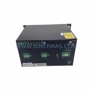
Pacific Scientific SCE906A2-002-01 Retrofit Servo Amplifier
SKU: EPC500 3183062451
Alfa Laval EPC500 3183062451 Service-Ready Spare Part