Original Industrial Spare Part
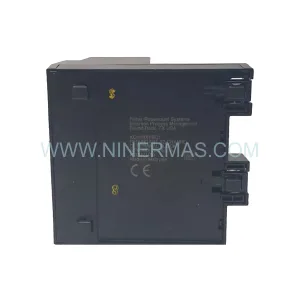
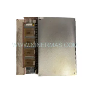
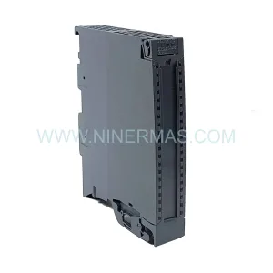
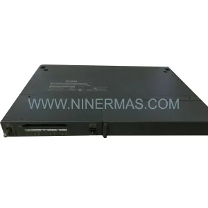
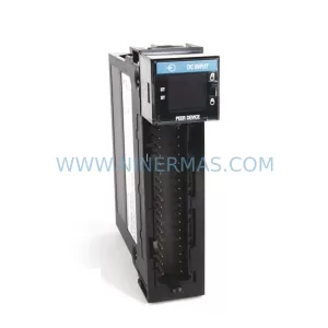
PLC 150-F60NBRB Retrofit-Compatible Motor Controller for Legacy Systems
Verify the part, confirm the platform family, and move straight into quotation with the right commercial details.
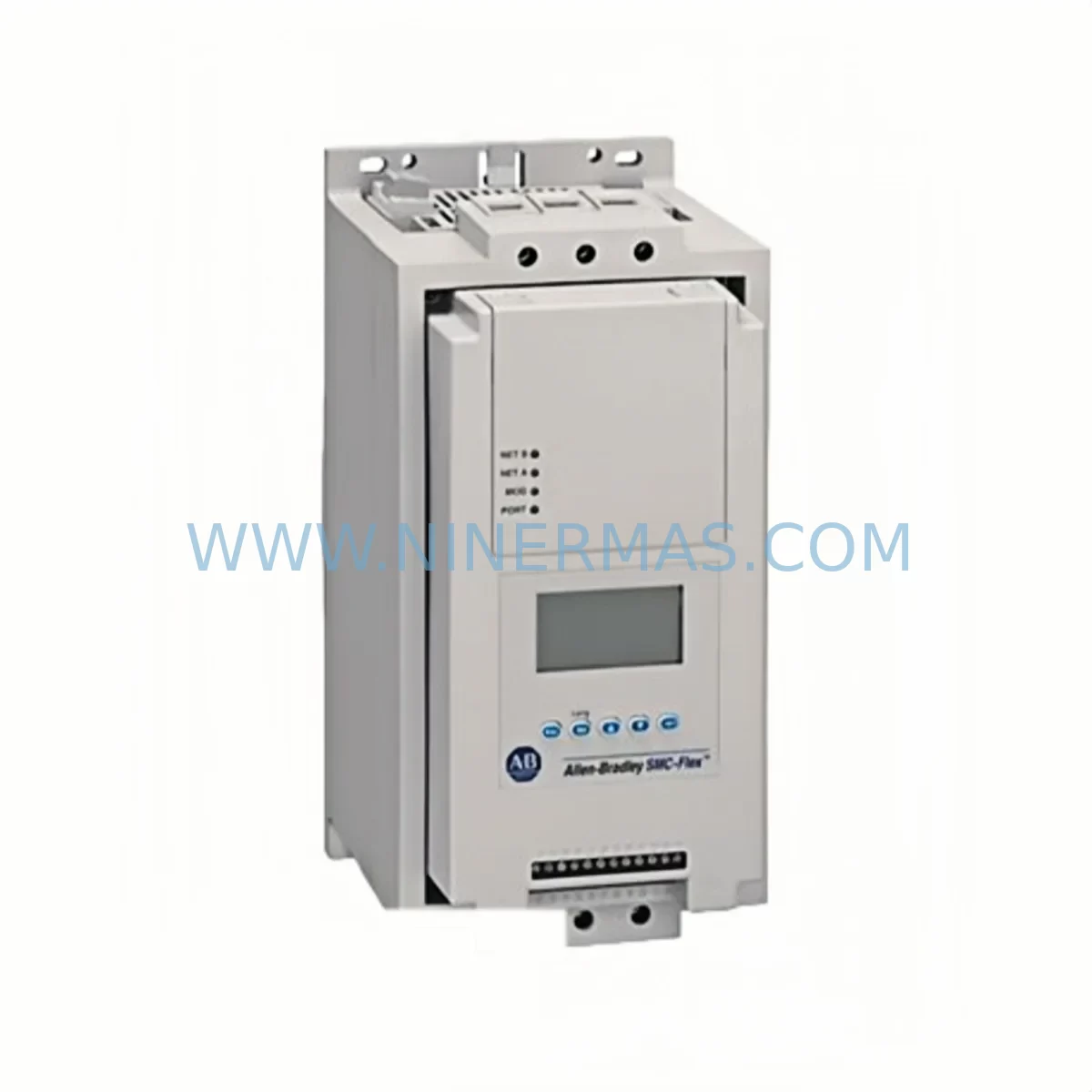
RFQ Ready
- SKU150-F60NBRB
- CategoryPLC & Industrial Automation Modules
- BrandPLC
- SupportAvailability, lead time, condition, and shipping coordination
How Buyers Usually Use This Page
- Confirm the exact part number and platform family before sending the quote request.
- Use direct email when quantity, condition, and destination are already defined internally.
- Switch to the broader brand or category archive when you need alternates nearby.
Series Navigation
Move through the most common platform families behind this part.
Product RFQ
Send this part directly for quotation.
Include quantity, required condition, destination country, and target delivery timing. Current reference: PLC 150-F60NBRB Retrofit-Compatible Motor Controller for Legacy Systems with SKU 150-F60NBRB.
PLC 150-F60NBRB Retrofit-Compatible Motor Controller: Seamless Legacy System Upgrade
The PLC 150-F60NBRB is a ruggedized smart motor controller engineered for demanding industrial environments and purpose-built to serve as a direct retrofit replacement for aging or discontinued motor control modules across a wide range of legacy automation platforms. Whether you are managing a planned system modernization or responding to an urgent component failure on the production floor, the 150-F60NBRB delivers the electrical compatibility, mechanical form factor, and communication protocol support needed to restore and extend the operational life of your existing control infrastructure with minimal disruption.
Industrial facilities running legacy motor control centers, distributed control systems, or older PLC-based architectures frequently encounter the challenge of sourcing reliable replacements for discontinued components. The 150-F60NBRB addresses this challenge directly by offering verified compatibility with common legacy backplane interfaces, standard terminal block wiring configurations, and widely deployed industrial communication protocols. This makes it an ideal candidate for retrofit projects where re-engineering the entire control cabinet is neither practical nor cost-effective.
Before committing to a retrofit installation, engineers and maintenance teams should systematically verify several critical parameters. Power supply capacity at the rack or cabinet level must be confirmed to support the 150-F60NBRB’s input voltage and current draw requirements, particularly in installations where multiple modules share a common power rail alongside components such as analog input modules, digital output cards, and communication interface modules. Terminal block wiring compatibility should be reviewed against the original field wiring documentation to ensure conductor gauge, terminal pitch, and signal polarity are correctly matched, avoiding the need for rewiring that would extend downtime.
Backplane interface alignment is another essential checkpoint. The 150-F60NBRB is designed to seat correctly in standard rack configurations commonly found in legacy motor control systems, but slot addressing and module identification settings must be configured to match the original module’s logical address within the control program. Failure to align module addressing will result in I/O mapping errors that prevent the controller from recognizing the replacement unit, requiring program modifications that should be planned and tested in advance.
Upgrade Compatibility Table
| Parameter | Details / Recommendation |
|---|---|
| SKU | 150-F60NBRB |
| Series | 150 Series Smart Motor Controller |
| Interface Compatibility | Standard backplane bus; verify slot pitch and connector type against legacy rack |
| Installation Requirements | DIN rail or panel mount; confirm available panel depth and clearance for wiring |
| Communication Compatibility | Supports common industrial protocols; verify against existing network configuration |
| Replacement Recommendation | Direct retrofit for discontinued 150-series motor control modules in legacy systems |
| Commissioning Focus | Module address configuration, I/O mapping verification, motor parameter re-entry |
| Warranty | 12-Month Warranty included with every unit |
Retrofit Planning for Existing Automation Systems
A successful retrofit of the 150-F60NBRB into an existing automation system requires careful coordination across multiple system layers. In installations where the motor controller interfaces with a programmable logic controller via a DeviceNet or EtherNet/IP network, the network node address of the replacement module must be set to match the original device’s address before the network is re-energized. This is particularly important in systems where the PLC program references the motor controller by its explicit network node, as an address mismatch will generate a communication fault that halts the associated control routine.
For facilities operating mixed-generation control cabinets that include both legacy analog signal modules and newer digital I/O expansion cards, the 150-F60NBRB’s signal interface must be validated against the existing field wiring. In many retrofit scenarios, the original motor controller was wired using older terminal block standards, and adapting to the 150-F60NBRB’s terminal configuration may require the use of signal isolation barriers or terminal adapter plates to maintain signal integrity without disturbing the existing field cable runs.
HMI screen configurations linked to the original motor controller’s status registers and fault codes should be reviewed and updated to reflect the 150-F60NBRB’s data map. In systems using older operator interface panels connected via serial communication links, the HMI tag database may need to be revised to correctly display motor run status, fault diagnostics, and parameter values sourced from the replacement module. This step is frequently overlooked during rapid replacement scenarios and can result in operators receiving incorrect status information after the retrofit is complete.
Power supply modules feeding the control rack should be load-tested after the 150-F60NBRB is installed to confirm that the total current draw remains within the power supply’s rated output capacity. In aging control cabinets where the original power supply is operating near its rated limit, the addition of a replacement motor controller with slightly different power consumption characteristics can push the supply into an overload condition. In such cases, upgrading the rack power supply in parallel with the motor controller replacement is strongly recommended to ensure long-term system stability.
Programming cables and configuration software compatible with the 150-series platform should be prepared in advance of the retrofit to allow on-site parameter entry and functional verification without relying on network-based configuration tools that may not be available in the field environment. Having the correct programming interface available on-site significantly reduces commissioning time and allows the maintenance team to complete motor parameter entry, protection threshold settings, and communication configuration before the system is returned to service.
Downtime Control During System Migration
Minimizing production downtime during a motor controller retrofit requires a structured pre-outage preparation process. Before the scheduled maintenance window, the existing 150-F60NBRB installation site should be fully documented, including photographs of the terminal wiring, a record of all module parameter settings, a backup of the PLC program, and a note of the current HMI screen configurations associated with the motor control loop. This documentation package serves as the reference baseline for the replacement installation and allows the commissioning team to restore the system to its pre-outage operational state as quickly as possible.
During the outage, the replacement 150-F60NBRB should be pre-configured off-line with all motor parameters, protection settings, and communication addresses entered and verified before the unit is installed in the rack. This pre-configuration approach eliminates the need for on-site parameter entry under time pressure and reduces the risk of configuration errors that could delay system restart. Once the module is installed and wired, a systematic power-up sequence should be followed, beginning with control power verification, followed by communication link establishment, I/O mapping confirmation, and finally a controlled motor start test under no-load conditions before the system is returned to full production operation.
Protecting the original PLC program logic during the migration is critical. The control program should not be modified unless a specific incompatibility with the 150-F60NBRB is identified during commissioning. In most retrofit scenarios, the replacement module is designed to present the same logical interface to the PLC as the original unit, allowing the existing program to operate without modification. Where program changes are unavoidable, they should be made in a staged manner with each change tested and verified before proceeding to the next, maintaining a clear audit trail of all modifications made during the retrofit process.
Retrofit Support FAQ
Q: Is the 150-F60NBRB a direct drop-in replacement for discontinued 150-series motor controllers?
A: The 150-F60NBRB is designed as a retrofit-compatible replacement for legacy 150-series motor control modules. Mechanical form factor, terminal wiring configuration, and communication protocol support are aligned with the original series specifications. Minor parameter re-entry and address configuration are typically required during commissioning, but no structural modifications to the control cabinet or PLC program are normally necessary.
Q: What commissioning steps are required after installing the 150-F60NBRB?
A: After physical installation and terminal wiring, the commissioning process includes setting the module’s network node address, entering motor nameplate parameters, configuring protection thresholds, verifying I/O mapping against the PLC program, and performing a controlled no-load motor start test. Communication link status should be confirmed on the network diagnostic tool before the system is returned to production.
Q: How is the 150-F60NBRB tested before shipment?
A: Every 150-F60NBRB unit undergoes functional testing prior to shipment, including power-on verification, communication interface testing, and output function checks. Units are shipped with test records available upon request. In-stock units are available for immediate dispatch to support urgent replacement requirements.
Q: What warranty coverage is provided with the 150-F60NBRB?
A: All 150-F60NBRB units supplied by NINERMAS are covered by a 12-month warranty against manufacturing defects and functional failures under normal operating conditions. Warranty support includes technical assistance for installation and commissioning issues identified within the warranty period.
| Product Series | Legacy |
|---|
Catalog Continuation
More PLC modules in the catalog.
Use the brand lane to compare nearby part numbers, platform-adjacent modules, and other inquiry-ready listings before sending your final RFQ.
Catalog Continuation
Alternative parts within PLC & Industrial Automation Modules.
Stay inside the same system family when you need substitutes, adjacent modules, or a broader shortlist for procurement review.
SKU: ZINT-541 3AUA00000658960
ABB ZINT-541 3AUA00000658960 Retrofit-Compatible Inverter Power Module
SKU: DSQC633 3HAC022286-001
ABB DSQC633 3HAC022286-001 Service-Ready Spare Part
SKU: 6SL3224-0BE33-7UA0
Siemens 6SL3224-0BE33-7UA0 Service-Ready Spare Part