Original Industrial Spare Part
Cedal FO 12.0007 Service-Ready Spare Part for Industrial Maintenance
Verify the part, confirm the platform family, and move straight into quotation with the right commercial details.
RFQ Ready
- SKUFO 12.0007
- CategoryPLC & Industrial Automation Modules
- BrandCedal
- SupportAvailability, lead time, condition, and shipping coordination
How Buyers Usually Use This Page
- Confirm the exact part number and platform family before sending the quote request.
- Use direct email when quantity, condition, and destination are already defined internally.
- Switch to the broader brand or category archive when you need alternates nearby.
Series Navigation
Move through the most common platform families behind this part.
Product RFQ
Send this part directly for quotation.
Include quantity, required condition, destination country, and target delivery timing. Current reference: Cedal FO 12.0007 Service-Ready Spare Part for Industrial Maintenance with SKU FO 12.0007.
Cedal FO 12.0007 Service-Ready Spare Part for Industrial Maintenance
The Cedal FO 12.0007 is a precision fiber optic sensor spare part engineered for demanding industrial automation environments. Whether you are managing a scheduled annual overhaul, responding to an unplanned line stoppage, or building a proactive spare parts inventory for your control cabinet, the FO 12.0007 delivers the original-specification performance your system requires. Sourced directly from verified supply channels, this component is tested prior to dispatch and backed by a 12-month warranty, giving maintenance engineers and procurement teams the confidence to act decisively when downtime risk is highest.
In modern manufacturing and process automation facilities, fiber optic sensors such as the Cedal FO 12.0007 serve as critical signal acquisition elements within photoelectric detection circuits, machine safety interlocks, and high-speed counting systems. A degraded or failed fiber optic tip can cascade into broader detection failures, triggering false fault codes across the PLC I/O rack and halting production. Keeping a verified replacement unit on the shelf eliminates the lead-time gap that turns a 30-minute swap into a multi-day procurement emergency.
Spare Maintenance Table
| Parameter | Specification |
|---|---|
| Part Number / SKU | FO 12.0007 |
| Brand | Cedal |
| Series | FO 12 Series |
| Component Type | Fiber Optic Sensor / Fiber Optic Cable Assembly |
| Fiber Core Diameter | Ø 1.0 mm (standard industrial grade) |
| Operating Temperature | -20°C to +70°C |
| Bending Radius (min.) | 10 mm |
| Jacket Material | PVC / Stainless Steel Armored (application dependent) |
| Compatibility | Cedal FO 12 Series amplifier heads; compatible with standard M4/M6 fiber optic receivers |
| Connector Type | Push-fit / SMA-compatible (verify with amplifier model) |
| Application Environment | Industrial automation, machine tool, packaging, conveyor, press line |
| Installation | Direct replacement; no recalibration required when paired with original amplifier |
| Origin | Italy (EU manufactured) |
| Warranty | 12 Months from date of shipment |
| Pre-shipment Testing | Yes — functional and optical continuity verified |
Maintenance Planning for Continuous Operation
Replacing the Cedal FO 12.0007 is rarely an isolated task. Experienced maintenance engineers know that a fiber optic sensor failure is often symptomatic of broader wear in the detection circuit or the surrounding control environment. When scheduling a replacement, it is best practice to simultaneously inspect the Cedal FO 12 Series amplifier head — the paired amplifier unit that processes the optical signal — for sensitivity drift or contaminated lens surfaces. A degraded amplifier will cause the new fiber to underperform immediately after installation.
Beyond the amplifier, the I/O input card on your PLC or safety controller that receives the FO 12.0007 signal should be verified for correct input voltage thresholds and response time settings. If your system uses a Siemens S7-300 or S7-1200 digital input module, confirm that the input filter time is configured appropriately for the sensor’s switching frequency. Similarly, if the fiber optic sensor feeds into a safety relay module — such as a Pilz PNOZ or Schmersal SRB series — the relay’s response time and reset logic should be validated after any sensor swap.
Power supply stability is another critical factor. The FO 12.0007 amplifier is typically powered from a 24 VDC rail within the control cabinet. Inspect your 24V DC SMPS (switched-mode power supply) — common units include Phoenix Contact QUINT or Siemens SITOP series — for output ripple and load regulation. A noisy power rail can cause intermittent switching behavior that mimics a faulty fiber, leading to misdiagnosis and unnecessary replacements.
For facilities running older systems, the terminal blocks and cable ferrules connecting the amplifier to the I/O module deserve attention. Loose or corroded Weidmüller or Phoenix Contact terminal connections introduce resistance that degrades signal integrity. During the same maintenance window, check the signal cable shielding and grounding — unshielded runs near VFD (variable frequency drive) output cables are a common source of electromagnetic interference that affects fiber optic amplifier output stability.
If your line uses a Profibus DP or Profinet communication module to relay sensor status to the SCADA or DCS layer, verify that the network segment remains healthy after the replacement. A brief bus interruption during the swap can trigger diagnostic alarms in the HMI that persist until manually cleared. Coordinate with your control room operator before isolating the sensor circuit. For facilities with Beckhoff EtherCAT I/O terminals or Mitsubishi MELSEC Q-series remote I/O, the same communication verification applies.
Finally, if the FO 12.0007 is part of a machine guarding or light curtain bypass circuit, ensure that the safety PLC program and any associated muting relay logic are re-validated after replacement in accordance with your site’s functional safety procedures (IEC 62061 / ISO 13849).
Site Replacement Workflow
Step 1 — Isolation and Lockout: De-energize the machine section and apply LOTO (Lockout/Tagout) per site procedure. Confirm 0V on the 24VDC supply rail feeding the amplifier.
Step 2 — Document Existing Configuration: Photograph the amplifier sensitivity setting (potentiometer position or digital display value) and note the fiber routing path and bend points before removal.
Step 3 — Remove the Old Fiber: Release the fiber from the amplifier head using the push-fit release mechanism. Avoid sharp bends during extraction. Inspect the amplifier lens for contamination — clean with isopropyl alcohol and a lint-free swab if required.
Step 4 — Install the Cedal FO 12.0007: Route the new fiber following the original path, respecting the minimum bending radius of 10 mm. Insert firmly into the amplifier head until the locking click is felt. Secure cable ties at original fixing points.
Step 5 — Power-Up and Sensitivity Adjustment: Re-energize the circuit. Restore the amplifier sensitivity to the documented setting. Perform a teach-in cycle if the amplifier supports auto-sensitivity. Verify the output LED status matches expected detection state.
Step 6 — Functional Test: Cycle the machine through its normal detection sequence. Confirm stable switching with no chattering or false triggers. Log the replacement in the maintenance management system (CMMS) with the new part serial number and date.
Step 7 — Return to Service: Remove LOTO, notify the control room, and confirm production restart. Update the spare parts inventory to trigger reorder of a replacement FO 12.0007 unit to maintain buffer stock.
Spare Parts Support FAQ
Q1: Is the Cedal FO 12.0007 a direct drop-in replacement for older FO 12 series fiber units?
Yes. The FO 12.0007 is designed as a form-fit-function replacement within the Cedal FO 12 Series. No amplifier reconfiguration is required when replacing a like-for-like unit. If you are upgrading from a discontinued predecessor model, verify the connector type and fiber diameter against your amplifier’s specification sheet before installation.
Q2: What is the recommended inventory quantity for a production facility running multiple FO 12 Series sensors?
Industry best practice for high-utilization fiber optic sensors in continuous production environments is to maintain a minimum of 2–3 units per active sensor position. For facilities with 10 or more FO 12.0007 installations, a standing buffer of 5–10 units is advisable to cover both emergency replacements and scheduled preventive maintenance cycles without triggering urgent procurement.
Q3: How is the FO 12.0007 tested before shipment?
Every unit undergoes optical continuity verification and functional output testing prior to dispatch. Units that do not meet original Cedal performance specifications are rejected. A test report is available upon request for quality-critical applications. All shipments are packaged in anti-static, impact-resistant packaging to prevent transit damage.
Q4: What does the 12-month warranty cover, and is long-term supply guaranteed?
The 12-month warranty covers manufacturing defects and functional failures under normal operating conditions. It does not cover damage resulting from incorrect installation, overvoltage, or mechanical abuse. Regarding long-term supply: we maintain a dedicated stock program for Cedal FO 12 Series components and can support blanket purchase orders for facilities requiring guaranteed annual supply commitments. Contact our technical sales team to discuss volume pricing and supply agreements.
| Product Series | Other series |
|---|
Catalog Continuation
Alternative parts within PLC & Industrial Automation Modules.
Stay inside the same system family when you need substitutes, adjacent modules, or a broader shortlist for procurement review.
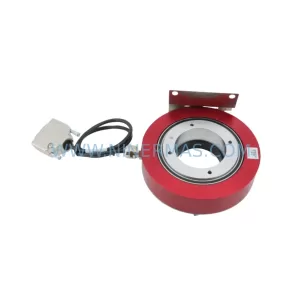
SKU: E19299450 E19299451 W/ MERCURY II 6000 ME-88-Y233-1 PCA-28430
Varian E19299450/E19299451 Service-Ready Spare Part
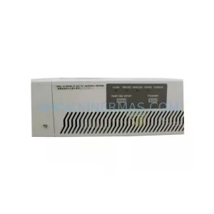
SKU: M-SPS1000RM-1F-0010-10061-0100-20003
Fuji M-SPS1000RM Retrofit Power Supply for Legacy Systems
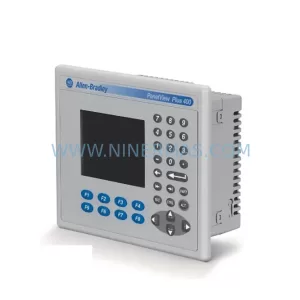
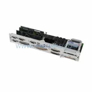
SKU: 6FC5357-0BB11-0AE1
Siemens 6FC5357-0BB11-0AE1 Retrofit NCU for Legacy Systems