Original Industrial Spare Part
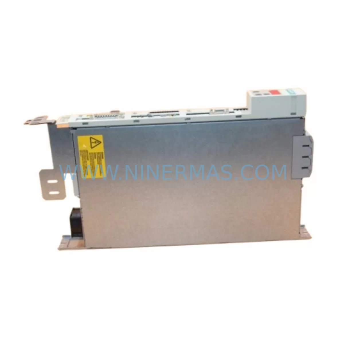
Siemens 6SE7012-0TP50 Retrofit-Compatible AC Drive
Verify the part, confirm the platform family, and move straight into quotation with the right commercial details.
RFQ Ready
- SKU6SE7012-0TP50
- CategoryPLC & Industrial Automation Modules
- BrandSiemens
- SupportAvailability, lead time, condition, and shipping coordination
How Buyers Usually Use This Page
- Confirm the exact part number and platform family before sending the quote request.
- Use direct email when quantity, condition, and destination are already defined internally.
- Switch to the broader brand or category archive when you need alternates nearby.
Series Navigation
Move through the most common platform families behind this part.
Product RFQ
Send this part directly for quotation.
Include quantity, required condition, destination country, and target delivery timing. Current reference: Siemens 6SE7012-0TP50 Retrofit-Compatible AC Drive with SKU 6SE7012-0TP50.
Siemens 6SE7012-0TP50 Retrofit-Compatible AC Drive: Legacy System Compatibility & Smooth Upgrade
The Siemens 6SE7012-0TP50 is a SIMOVERT Compact Plus series AC variable frequency drive designed for industrial motor control applications. As legacy automation systems age and original spare parts reach end-of-life, the 6SE7012-0TP50 has become a critical retrofit and replacement component for engineers managing older production lines, control cabinets, and drive systems. Whether you are replacing a discontinued unit, upgrading a legacy panel, or migrating from an obsolete control platform, this drive offers a reliable, retrofit-compatible solution backed by 12 months of warranty coverage and verified pre-shipment testing.
When planning a retrofit or replacement using the 6SE7012-0TP50, engineers must carefully evaluate several key compatibility factors before installation. Power supply capacity is the first checkpoint — confirm that the existing cabinet power rail can support the drive’s input voltage and current draw without requiring additional transformer upgrades. Terminal wiring must be reviewed against the original drive’s connection diagram, as differences in control terminal layout between the 6SE7012-0TP50 and its predecessor models may require rewiring of analog reference signals, digital I/O, and relay outputs. Backplane interface compatibility should also be verified if the drive is being installed into a shared rack or bus system alongside other SIMOVERT modules.
Module addressing is another critical step, particularly in systems where the drive communicates over PROFIBUS-DP or USS protocol. The parameter set from the legacy unit — including ramp times, frequency limits, motor nameplate data, and PID configurations — must be re-entered or transferred to the replacement unit. If the original system used a SIMATIC S5 or early S7 controller, confirm that the communication module, such as a CB15 or SCB2 communications board, is compatible with the 6SE7012-0TP50’s parameter interface. In systems using a SIMATIC S7-300 or S7-400 PLC with a CP 342-5 or CP 443-5 PROFIBUS master, the GSD file and hardware configuration in STEP 7 may need to be updated to reflect the replacement drive’s device identity.
Upgrade Compatibility Table
| Parameter | Details |
|---|---|
| SKU / Model | 6SE7012-0TP50 |
| Series | SIMOVERT Compact Plus |
| Input Voltage | 3-phase AC, 380–480V |
| Output Power | 1.1 kW (typical for 0TP50 frame) |
| Communication Interface | PROFIBUS-DP / USS (via optional CB) |
| Mounting / Installation | Panel mount, DIN rail compatible |
| Replacement Compatibility | Direct retrofit for SIMOVERT Compact Plus legacy units |
| Control Terminal Wiring | Verify against original wiring diagram before installation |
| Backplane / Rack Interface | Confirm slot and bus compatibility in shared rack systems |
| Communication Protocol Migration | PROFIBUS-DP, USS; GSD file update may be required |
| HMI Screen Compatibility | Re-map drive parameters if using OP7, OP17, or TP270 panels |
| Pre-Shipment Testing | Yes — function verified before dispatch |
| Warranty | 12 Months |
Retrofit Planning for Existing Automation Systems
A successful retrofit using the 6SE7012-0TP50 requires a structured approach to component identification and sequencing. In most legacy control cabinets, the drive is installed alongside a 6SE7090-0XX84-0AB0 SIMOVERT operator panel or a basic PMU (Parameterization Unit), which must be retained or replaced with a compatible interface during the upgrade. If the system uses a 6SY7000-0AD87 power supply module or a shared DC bus configuration, the bus voltage and load distribution must be recalculated to accommodate the replacement drive.
For systems with distributed I/O, the 6SE7012-0TP50 may interface with ET 200M or ET 200S remote I/O stations via PROFIBUS-DP. In these configurations, the IM 153-2 interface module and associated SM 321 digital input or SM 331 analog input modules must remain correctly addressed and configured in the STEP 7 hardware table. Any changes to the drive’s PROFIBUS node address must be reflected in the PLC program to avoid communication faults at startup.
Signal isolation is another consideration in older plants where analog reference signals (0–10V or 4–20mA) are routed over long cable runs. Installing a signal isolator or repeater between the PLC analog output module and the drive’s reference input terminal can prevent noise-induced instability in speed control. In systems where the 6SE7012-0TP50 replaces a unit connected to a SIMATIC HMI such as a TP270 or MP277, the HMI project may require screen updates to reflect the new drive’s parameter addresses and fault code mapping.
Programming cable compatibility should also be confirmed. If the original commissioning was performed using a PC adapter with STEP 7 or DriveMonitor software, the same toolchain can typically be used for the 6SE7012-0TP50, provided the correct firmware version is installed. For systems using a 6ES7 972-0CB20-0XA0 PC adapter or MPI/PROFIBUS interface, no hardware changes are typically required for parameter upload and download.
Downtime Control During System Migration
Minimizing production downtime during a drive replacement is a primary concern for maintenance engineers. When replacing the 6SE7012-0TP50 in a live production environment, the recommended approach is to pre-configure the replacement unit offline using DriveMonitor or STARTER software before the scheduled maintenance window. All motor parameters, ramp settings, frequency limits, and communication addresses should be loaded and verified on the bench prior to installation.
During the physical swap, the original terminal wiring should be photographed and documented before disconnection. Control wiring, power terminals, and any optional communication boards such as the CB15 or SCB2 should be transferred or reconnected in sequence according to the original wiring diagram. After installation, a controlled test run at reduced load is recommended before returning the drive to full production speed, allowing the engineering team to verify speed reference tracking, fault relay behavior, and communication link integrity with the upstream PLC or SCADA system.
In systems where continuous process control is required, a parallel commissioning approach may be used — where the replacement drive is installed in a bypass configuration and tested under load before the original unit is fully decommissioned. This approach is particularly effective in pump, fan, and conveyor applications where brief speed variations are tolerable during the switchover period. Throughout the migration, the original PLC program logic should remain unchanged to preserve control continuity and reduce the risk of introducing new faults into the automation sequence.
Retrofit Support FAQ
Q: Is the 6SE7012-0TP50 a direct drop-in replacement for other SIMOVERT Compact Plus models?
A: The 6SE7012-0TP50 is designed as a retrofit-compatible replacement within the SIMOVERT Compact Plus series. Physical dimensions, mounting footprint, and terminal layout are consistent with the series standard, but engineers should verify power rating, control terminal wiring, and communication board compatibility against the specific unit being replaced before installation.
Q: What commissioning steps are required after installation?
A: After physical installation, the drive must be parameterized with motor nameplate data, ramp times, frequency limits, and communication settings. If the original parameter set was saved using DriveMonitor or STARTER, it can be uploaded directly to the replacement unit. A no-load test followed by a loaded test run is recommended before returning to full production.
Q: How is terminal wiring compatibility verified before installation?
A: Compare the original drive’s wiring diagram with the 6SE7012-0TP50 terminal layout diagram from the technical documentation. Pay particular attention to analog reference inputs, digital I/O assignments, relay output wiring, and any optional communication board connections. Differences in terminal numbering between legacy and replacement units are common and must be resolved before energizing the drive.
Q: What does the 12-month warranty cover, and is pre-shipment testing included?
A: Every 6SE7012-0TP50 unit is function-tested before dispatch to verify basic operation. The 12-month warranty covers manufacturing defects and operational failures under normal industrial use conditions. Units are shipped with documentation confirming test completion. For warranty claims or technical support, contact our team directly.
| Product Series | SIMOVERT |
|---|---|
| Country of Origin | DE |
Catalog Continuation
More Siemens modules in the catalog.
Use the brand lane to compare nearby part numbers, platform-adjacent modules, and other inquiry-ready listings before sending your final RFQ.
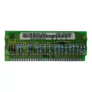
SKU: 6SE7038-6EK84-1BH0
Siemens 6SE7038-6EK84-1BH0 Retrofit Drive Control Module
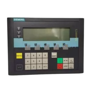
SKU: 6SL3055-0AA00-4CA5
Siemens 6SL3055-0AA00-4CA5 Retrofit-Compatible Operator Panel for Legacy Systems
Catalog Continuation
Alternative parts within PLC & Industrial Automation Modules.
Stay inside the same system family when you need substitutes, adjacent modules, or a broader shortlist for procurement review.
SKU: OZDPROFI12MG12
Hirschmann OZDPROFI12MG12 Spare Part for Industrial Maintenance
SKU: 07025-0000-70-1-04
KONTRON 07025-0000-70-1-04 Service-Ready Spare Part