Original Industrial Spare Part
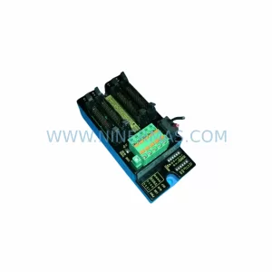
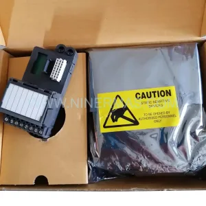
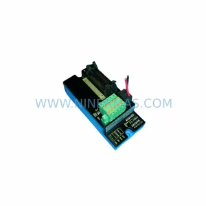
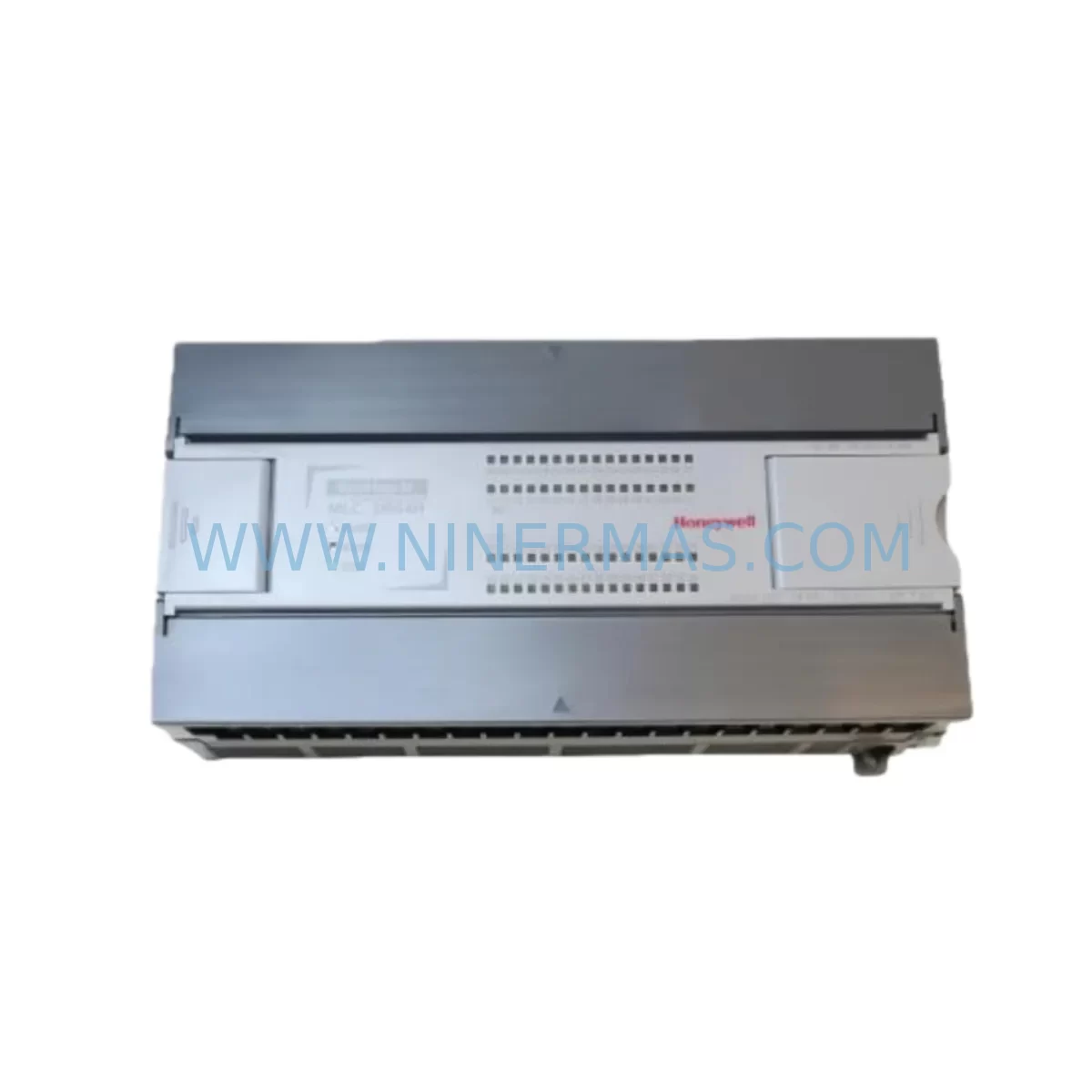
Honeywell MLC-DR32H Retrofit-Compatible Relay Digital Output Module
Verify the part, confirm the platform family, and move straight into quotation with the right commercial details.
RFQ Ready
- SKUMLC-DR32H
- CategoryDCS Distributed Control Systems
- BrandHoneywell
- SupportAvailability, lead time, condition, and shipping coordination
How Buyers Usually Use This Page
- Confirm the exact part number and platform family before sending the quote request.
- Use direct email when quantity, condition, and destination are already defined internally.
- Switch to the broader brand or category archive when you need alternates nearby.
Series Navigation
Move through the most common platform families behind this part.
Product RFQ
Send this part directly for quotation.
Include quantity, required condition, destination country, and target delivery timing. Current reference: Honeywell MLC-DR32H Retrofit-Compatible Relay Digital Output Module with SKU MLC-DR32H.
Honeywell MLC-DR32H Retrofit-Compatible Relay Digital Output Module: Legacy System Compatibility and Smooth Upgrade
The Honeywell MLC-DR32H is a 32-channel relay digital output module designed for the MasterLogic-200R series programmable logic controller platform. As industrial facilities face increasing pressure to extend the operational life of legacy automation systems or migrate to modern control architectures, the MLC-DR32H serves as a critical retrofit-compatible component — enabling engineers to replace discontinued relay output modules, restore degraded I/O capacity, and maintain production continuity without a full system overhaul.
Whether you are managing a brownfield retrofit project, sourcing end-of-life spare parts for an aging control cabinet, or planning a phased migration from an older Honeywell MasterLogic platform to a current-generation controller, the MLC-DR32H provides a verified drop-in replacement path that minimizes engineering rework and reduces commissioning risk on the plant floor.
Upgrade Compatibility Table
| Parameter | Details |
|---|---|
| Module Model | Honeywell MLC-DR32H |
| Series | MasterLogic-200R |
| Module Type | Relay Digital Output Module |
| Output Channels | 32 Relay Output Channels |
| Backplane Interface | MasterLogic-200R Series Rack / Backplane Slot |
| Installation Requirement | Compatible with MasterLogic-200R base rack; verify slot addressing before installation |
| Terminal Wiring | Field-side terminal block; confirm existing wiring gauge and relay load ratings |
| Communication Compatibility | Native MasterLogic-200R backplane communication; no additional protocol conversion required for same-series replacement |
| Replacement Recommendation | Direct replacement for failed or discontinued MLC-DR32H units in existing MasterLogic-200R racks |
| Commissioning Focus | Module address verification, relay output force test, program logic scan confirmation, HMI tag mapping review |
| Warranty | 12-Month Warranty — all units ship after functional output test |
Retrofit Planning for Existing Automation Systems
Successful integration of the MLC-DR32H into an existing control system begins well before the module arrives on site. Retrofit planning for MasterLogic-200R-based systems typically involves a coordinated review of the entire control cabinet architecture — not just the failed output module itself.
Start by auditing the MasterLogic-200R base rack and confirming available backplane slots. In multi-rack configurations, the rack expansion cables and inter-rack communication links must be inspected for integrity before a new relay output module is inserted. If the system uses a MLC-CPU module (the central processing unit of the MasterLogic-200R platform), verify that the firmware version supports the MLC-DR32H’s I/O configuration without requiring a CPU update — a step that is frequently overlooked during emergency spare part replacements.
Power capacity is a common constraint in aging control cabinets. The MLC-PS power supply module feeding the rack must be confirmed to have sufficient residual capacity to support the relay output module’s coil energization load, particularly when multiple relay channels switch simultaneously under full load. If the existing power supply is already operating near its rated output, a parallel or upgraded power supply module should be sourced alongside the MLC-DR32H to prevent nuisance trips during commissioning.
On the field wiring side, the relay output terminal block connections must be mapped against the original I/O list. Relay output modules in legacy systems are frequently wired to motor starters, solenoid valves, pilot lights, and interlock circuits — all of which carry different inductive load characteristics. Confirm that the MLC-DR32H’s relay contact ratings (voltage, current, and load type) are compatible with the connected field devices before energizing the outputs.
For systems that have undergone partial upgrades, it is common to find a mix of older MLC-DI16H digital input modules and newer I/O modules sharing the same rack. In these mixed configurations, module slot addressing must be carefully re-verified in the PLC program after the MLC-DR32H is installed, as address conflicts between old and new modules can cause unexpected output behavior during the first program scan after power-up.
If the retrofit scope extends beyond a single module replacement and includes communication protocol migration — for example, transitioning field devices from hardwired relay logic to a Modbus RTU or PROFIBUS DP network — a MLC-COM communication module may need to be added to the rack alongside the relay output module. This is particularly relevant in projects where the customer is consolidating multiple legacy control panels into a single modernized control cabinet with centralized SCADA supervision.
HMI screen updates are another frequently underestimated element of relay output module retrofits. If the plant uses a Honeywell HMI terminal or a third-party operator panel connected to the MasterLogic-200R CPU, the output tag addresses associated with the MLC-DR32H channels must be confirmed against the HMI project database. Mismatched tag addresses between the PLC program and the HMI screen can result in incorrect status displays or failed remote output commands — a critical issue in processes where operators rely on HMI-initiated relay switching for equipment control.
Signal isolation is another consideration when the MLC-DR32H is used in environments with high electrical noise, such as variable frequency drive (VFD) panels or large motor control centers. In these applications, signal isolator modules or interposing relay barriers between the MLC-DR32H output terminals and the field devices help protect the module’s relay contacts from voltage spikes and extend service life. Sourcing these isolators as part of the retrofit kit — rather than as an afterthought during commissioning — significantly reduces the risk of premature relay contact failure after the system is returned to service.
Finally, for projects involving programming cable access to the MasterLogic-200R CPU for program backup and restoration, confirm that the engineering workstation software version is compatible with the existing CPU firmware before beginning any program modifications related to the new relay output module configuration.
Downtime Control During System Migration
Minimizing unplanned downtime is the primary operational concern when replacing a relay digital output module in a live production environment. For the Honeywell MLC-DR32H, a structured hot-swap or controlled shutdown procedure is essential to protect both the existing program logic and the field devices connected to the relay outputs.
Before removing the failed or degraded MLC-DR32H from the rack, perform a complete program backup from the MasterLogic-200R CPU to an offline engineering workstation. This backup preserves the current output force states, relay latch conditions, and any runtime data that may be lost during the module swap. If the CPU supports online program monitoring, use this capability to confirm which relay output channels are currently active before de-energizing the module — this prevents unexpected field device activation or deactivation during the replacement sequence.
Where process conditions allow, place the affected control loop in manual mode at the DCS or SCADA level before physically removing the MLC-DR32H. This step decouples the relay output channels from automatic program control and allows the field operator to maintain process stability using local manual controls while the module is being replaced in the control cabinet.
After installing the new MLC-DR32H, perform a channel-by-channel relay output force test using the PLC programming software before returning the system to automatic control. This test confirms that each of the 32 relay channels responds correctly to program commands, that the terminal wiring is correctly connected, and that no relay contacts are welded or open-circuit from the previous failure mode. Document the test results as part of the retrofit commissioning record.
For multi-rack systems where the MLC-DR32H is installed in an expansion rack connected to the main CPU rack via a rack expansion cable, verify that the inter-rack communication link is re-established after the module swap and that the CPU recognizes the new module at the correct rack and slot address. A missed rack communication fault can cause the CPU to flag the entire expansion rack as offline, disabling all I/O in that rack — not just the replaced relay output module.
By following a disciplined replacement and commissioning sequence, most MLC-DR32H module swaps in MasterLogic-200R systems can be completed within a planned maintenance window of two to four hours, including program backup, physical replacement, wiring verification, output force testing, and return to automatic control.
Retrofit Support FAQ
Q1: Is the Honeywell MLC-DR32H a direct drop-in replacement for the original module in a MasterLogic-200R rack?
Yes. The MLC-DR32H is designed for direct installation into MasterLogic-200R series racks using the standard backplane slot interface. No hardware modification to the rack or backplane is required. However, you should verify the module slot address in the PLC program matches the physical installation slot before returning the system to automatic control.
Q2: What pre-shipment testing is performed on the MLC-DR32H before delivery?
All MLC-DR32H units supplied by NINERMAS undergo functional output testing prior to shipment. Each relay output channel is verified for correct switching operation. Units are shipped with a 12-month warranty covering manufacturing defects and functional failures under normal operating conditions.
Q3: Can the MLC-DR32H be used in a system that has been partially upgraded with newer I/O modules?
Yes, provided the rack and backplane remain MasterLogic-200R compatible. In mixed-module configurations, pay particular attention to slot addressing in the PLC program to avoid address conflicts between the MLC-DR32H and any newer I/O modules installed in adjacent slots. Confirm the CPU firmware version supports the mixed module configuration before commissioning.
Q4: What is the typical lead time and stock availability for the MLC-DR32H?
NINERMAS maintains inventory of the MLC-DR32H to support emergency replacement and planned retrofit projects. Contact our sales team at sale@ninermas.com or +0086 187 5021 5667 for current stock status and delivery schedule. All units are supplied with a 12-month warranty and functional test documentation.
—
| Product Series | MasterLogic |
|---|---|
| Country of Origin | US |
Catalog Continuation
More Honeywell modules in the catalog.
Use the brand lane to compare nearby part numbers, platform-adjacent modules, and other inquiry-ready listings before sending your final RFQ.
Catalog Continuation
Alternative parts within DCS Distributed Control Systems.
Stay inside the same system family when you need substitutes, adjacent modules, or a broader shortlist for procurement review.