Original Industrial Spare Part
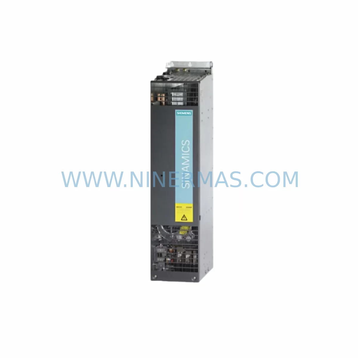
Siemens 6SL3330-6TE37-3AA3 Retrofit Smart Line Module
Verify the part, confirm the platform family, and move straight into quotation with the right commercial details.
RFQ Ready
- SKU6SL3330-6TE37-3AA3
- CategoryPLC & Industrial Automation Modules
- BrandSiemens
- SupportAvailability, lead time, condition, and shipping coordination
How Buyers Usually Use This Page
- Confirm the exact part number and platform family before sending the quote request.
- Use direct email when quantity, condition, and destination are already defined internally.
- Switch to the broader brand or category archive when you need alternates nearby.
Series Navigation
Move through the most common platform families behind this part.
Product RFQ
Send this part directly for quotation.
Include quantity, required condition, destination country, and target delivery timing. Current reference: Siemens 6SL3330-6TE37-3AA3 Retrofit Smart Line Module with SKU 6SL3330-6TE37-3AA3.
Siemens 6SL3330-6TE37-3AA3 Retrofit-Compatible Smart Line Module for Legacy SINAMICS S120 Systems
The Siemens 6SL3330-6TE37-3AA3 is a high-power Smart Line Module (SLM) within the SINAMICS S120 booksize cabinet platform, designed to supply regulated DC bus voltage to connected Motor Modules and auxiliary drive components. As legacy SINAMICS S120 infrastructure ages and original units reach end-of-service life, the 6SL3330-6TE37-3AA3 has become a critical retrofit and replacement component for engineers managing aging production lines, control cabinet upgrades, and drive system modernization projects across heavy industry, steel, paper, and process automation sectors.
NINERMAS maintains verified stock of the 6SL3330-6TE37-3AA3 with full functional testing prior to shipment, backed by a 12-month warranty. Each unit is inspected for DC bus integrity, DRIVE-CLiQ communication readiness, and power stage condition before dispatch.
Upgrade Compatibility Table
| Parameter | Details |
|---|---|
| SKU / Part Number | 6SL3330-6TE37-3AA3 |
| Series | SINAMICS S120 Booksize Cabinet |
| Module Type | Smart Line Module (SLM) |
| Communication Interface | DRIVE-CLiQ |
| Installation Format | Booksize Cabinet Mount |
| Replaces / Compatible With | Earlier SINAMICS S120 SLM variants; legacy MASTERDRIVES MC/VC line modules (with adaptation) |
| Backplane / Rack Interface | DC bus bar connection; compatible with S120 cabinet infrastructure |
| Commissioning Tool | STARTER / Startdrive (TIA Portal) |
| Retrofit Complexity | Medium — requires power capacity verification and DRIVE-CLiQ topology update |
| Warranty | 12 Months (NINERMAS) |
Retrofit Planning for Existing Automation Systems
When integrating the 6SL3330-6TE37-3AA3 into an existing drive cabinet, the first step is confirming that the incoming supply transformer and upstream circuit breaker can support the module’s rated input current. Many older installations originally sized for smaller MASTERDRIVES or early S120 Active Line Modules may require a supply capacity review before the new Smart Line Module is energized.
The DC bus bar arrangement within the cabinet must be inspected for compatibility with the 6SL3330-6TE37-3AA3’s bus connection geometry. In retrofit scenarios where the cabinet was originally built around a different booksize frame, spacer plates or bus bar adapters may be required. Engineers should also verify that the SINAMICS S120 Control Unit — typically a CU320-2 DP or CU320-2 PN — has sufficient firmware version support for the replacement SLM, as older CU firmware may not enumerate the new module correctly via DRIVE-CLiQ.
The DRIVE-CLiQ topology must be updated in the project after physical installation. Using STARTER or Startdrive within TIA Portal, the engineer should perform an automatic topology detection, confirm the new SLM is recognized at the correct DRIVE-CLiQ port, and re-assign drive objects accordingly. If the original project file references the old module’s firmware version or device identifier, a device replacement procedure within the commissioning tool is required before downloading the updated configuration.
For systems that also include SINAMICS S120 Double Motor Modules (such as the 6SL3120-2TE21-8AA3 or 6SL3120-2TE13-0AA3) or Single Motor Modules on the same DC bus, the engineer must verify that the total connected motor load does not exceed the new SLM’s rated output power. The 6SL3330-6TE37-3AA3 is a high-capacity unit, but in multi-axis cabinet configurations, a full load calculation is still recommended.
Terminal wiring on the line-side connection should be re-torqued to specification during installation. The PE (protective earth) connection and the pre-charging circuit wiring — often routed through a SINAMICS S120 Braking Module or a line filter such as the 6SL3000-0BE31-6DA0 — must be verified for continuity and correct phase assignment. Incorrect phase sequencing on the AC input will prevent the SLM from completing its pre-charge sequence and will generate a fault on the Control Unit.
Where the original system used a SINAMICS S120 Voltage Sensing Module (VSM10) for supply voltage monitoring, confirm that the VSM10 is still correctly wired and recognized in the DRIVE-CLiQ chain after the SLM replacement. Some retrofit projects also involve migrating from PROFIBUS DP to PROFINET communication at the same time; in these cases, the CU320-2 PN and updated CBE20 Communication Board should be configured before the new SLM is commissioned to avoid topology conflicts.
If the plant uses a SIMATIC S7-300 or S7-400 PLC as the higher-level controller, verify that the existing drive parameter blocks (DPV1 or standard DP cyclic data) remain compatible after the SLM swap. In most cases, the PLC program does not require modification if the drive object structure is preserved, but a full I/O signal check — including ready signals, fault outputs, and speed reference channels — should be completed before returning the line to production.
For HMI integration, if the plant uses a SIMATIC HMI TP900 or TP1500 panel connected via PROFINET or MPI, the drive status tags mapped to the SLM’s operating state should be verified against the updated drive object numbering. Screen-level alarm messages referencing the old module’s fault codes may need to be updated in the HMI project to reflect the new SLM’s diagnostic structure.
Downtime Control During System Migration
Minimizing production downtime during a Smart Line Module replacement requires careful pre-staging. Before the scheduled maintenance window, the engineer should export the complete drive project from STARTER or Startdrive, back up all parameter sets for the Control Unit and each connected Motor Module, and document the existing DRIVE-CLiQ wiring topology with photographs or a wiring diagram. This preparation ensures that if any step during the physical swap introduces an unexpected fault, the original configuration can be restored quickly.
During the replacement window, the DC bus should be fully discharged and verified with a voltmeter before any connections are disturbed — the S120 cabinet’s DC bus capacitors retain dangerous charge levels for several minutes after power-off. Once the 6SL3330-6TE37-3AA3 is physically installed and all connections are torqued, power can be restored in stages: first energize the Control Unit and confirm DRIVE-CLiQ topology detection, then enable the SLM pre-charge sequence, and finally release the Motor Modules for operation.
A phased recommissioning approach — testing each drive axis individually before enabling full production speed — reduces the risk of a multi-axis fault cascade on first startup. Speed reference ramp rates should be set conservatively for the initial test run, with the original ramp parameters restored only after stable operation is confirmed across all axes. This approach typically allows a complete SLM replacement and recommissioning to be completed within a single planned maintenance shift, keeping unplanned downtime to a minimum.
Retrofit Support FAQ
Q: Is the 6SL3330-6TE37-3AA3 a direct drop-in replacement for an older SINAMICS S120 Smart Line Module?
A: In most cases, yes — provided the cabinet infrastructure, DC bus bar geometry, and DRIVE-CLiQ wiring are compatible. A firmware check on the Control Unit is recommended before installation to confirm the CU supports the replacement SLM’s device profile.
Q: What commissioning steps are required after installing the replacement module?
A: After physical installation, connect to the drive system using STARTER or Startdrive, perform an automatic DRIVE-CLiQ topology scan, confirm the new SLM is correctly identified, and download the updated configuration. A full parameter comparison between the backup and the new configuration is recommended before enabling the drive.
Q: Can NINERMAS supply the 6SL3330-6TE37-3AA3 with pre-shipment functional testing?
A: Yes. All units are tested for DC bus integrity, DRIVE-CLiQ communication, and power stage condition prior to dispatch. A test report is available upon request.
Q: What warranty does NINERMAS provide on this unit?
A: NINERMAS provides a 12-month warranty on the 6SL3330-6TE37-3AA3 covering manufacturing defects and functional failures under normal operating conditions. Warranty support includes technical assistance for installation and commissioning queries.
| Product Series | SINAMICS |
|---|---|
| Country of Origin | DE |
Catalog Continuation
More Siemens modules in the catalog.
Use the brand lane to compare nearby part numbers, platform-adjacent modules, and other inquiry-ready listings before sending your final RFQ.
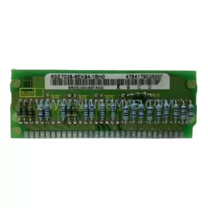
SKU: 6SE7038-6EK84-1BH0
Siemens 6SE7038-6EK84-1BH0 Retrofit Drive Control Module
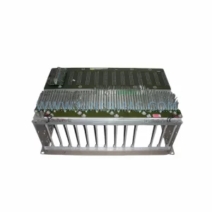
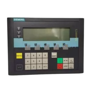
SKU: 6SL3055-0AA00-4CA5
Siemens 6SL3055-0AA00-4CA5 Retrofit-Compatible Operator Panel for Legacy Systems
Catalog Continuation
Alternative parts within PLC & Industrial Automation Modules.
Stay inside the same system family when you need substitutes, adjacent modules, or a broader shortlist for procurement review.
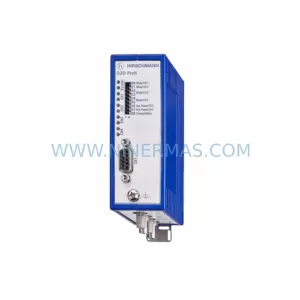
SKU: OZDPROFI12MG12
Hirschmann OZDPROFI12MG12 Spare Part for Industrial Maintenance
SKU: 07025-0000-70-1-04
KONTRON 07025-0000-70-1-04 Service-Ready Spare Part