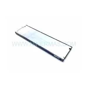
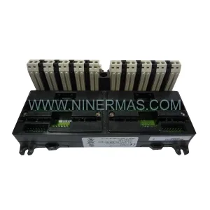
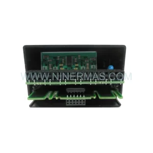
Original Industrial Spare Part
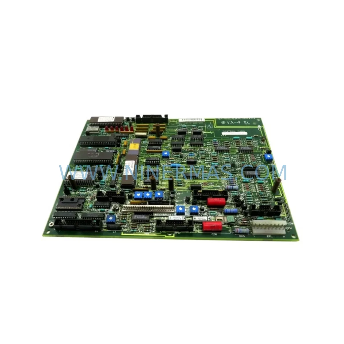
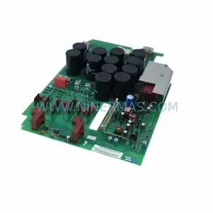
GE 531X133PRUALG1 Retrofit-Compatible Process Interface Board
Verify the part, confirm the platform family, and move straight into quotation with the right commercial details.
RFQ Ready
- SKU531X133PRUALG1
- CategoryPLC & Industrial Automation Modules
- BrandGE
- SupportAvailability, lead time, condition, and shipping coordination
How Buyers Usually Use This Page
- Confirm the exact part number and platform family before sending the quote request.
- Use direct email when quantity, condition, and destination are already defined internally.
- Switch to the broader brand or category archive when you need alternates nearby.
Series Navigation
Move through the most common platform families behind this part.
Product RFQ
Send this part directly for quotation.
Include quantity, required condition, destination country, and target delivery timing. Current reference: GE 531X133PRUALG1 Retrofit-Compatible Process Interface Board with SKU 531X133PRUALG1.
GE 531X133PRUALG1 Retrofit-Compatible Process Interface Board: Legacy System Compatibility & Smooth Upgrade
The GE 531X133PRUALG1 is a process interface board engineered for industrial control environments where legacy GE Drive and control platform continuity is paramount. As automation engineers and maintenance teams face the growing challenge of sourcing discontinued spare parts, the 531X133PRUALG1 serves as a critical retrofit-compatible replacement that bridges the gap between aging infrastructure and modern operational demands. Whether you are managing a turbine control panel, a legacy drive cabinet, or a distributed control system built on GE’s Mark series architecture, this board provides the signal conditioning, process interfacing, and backplane communication capabilities required to restore and sustain system functionality without a full platform overhaul.
Procurement teams and plant engineers working with GE’s 531X series boards understand that these components are deeply embedded in long-running production lines. The 531X133PRUALG1 is commonly found in applications alongside companion boards such as the 531X111PSHARG1 power supply board and the 531X307LTBAFG3 terminal board, both of which share the same backplane architecture and connector pinout standards. When planning a retrofit, it is essential to verify that the replacement board matches the original slot assignment and that the backplane interface — typically a 96-pin DIN connector — is undamaged and properly seated.
Upgrade Compatibility Table
| Parameter | Details |
|---|---|
| SKU / Part Number | 531X133PRUALG1 |
| Brand / Manufacturer | GE (General Electric / GE Fanuc) |
| Series | 531X Series — GE Drive & Turbine Control Platform |
| Board Function | Process Interface / Signal Conditioning |
| Backplane Interface | 96-pin DIN connector, compatible with GE Mark IV / Mark V / Mark VI racks |
| Installation Requirement | Slot-specific installation; verify rack address and module position before insertion |
| Communication Compatibility | Compatible with GE ARCNET and serial communication backbones used in legacy turbine control panels |
| Replacement Recommendation | Direct retrofit replacement for legacy 531X133 series boards; verify firmware revision compatibility |
| Commissioning Focus | Confirm I/O address mapping, terminal wiring continuity, and HMI signal tag alignment before power-up |
| Warranty | 12-Month Warranty — covers manufacturing defects and functional failure under normal operating conditions |
Retrofit Planning for Existing Automation Systems
A successful retrofit using the GE 531X133PRUALG1 begins well before the board arrives on-site. Maintenance engineers should start by auditing the existing control cabinet layout, documenting the current slot configuration of the rack, and confirming the power supply capacity of the 531X111PSHARG1 or equivalent power board. Insufficient power headroom is one of the most common causes of post-retrofit instability, particularly in cabinets where additional I/O expansion modules such as the 531X121PCHARG1 have been added over the years without a corresponding power budget review.
Terminal wiring is the next critical checkpoint. The 531X133PRUALG1 interfaces with field signals through a dedicated terminal board — in many installations this is the 531X307LTBAFG3 or a functionally equivalent LAN terminal board. Engineers must verify that each field wire is correctly mapped to its terminal point, that shield grounds are properly landed, and that no wiring has degraded due to heat cycling or vibration over the system’s service life. Any discrepancy in terminal assignment between the old board and the replacement can result in incorrect process readings or, in worst cases, unintended actuator commands.
For systems that include a GE Mark VI controller or a legacy Mark V turbine control panel, the module address configuration stored in the EEPROM or DIP switch settings of the 531X133PRUALG1 must match the address expected by the controller. Mismatched addresses will prevent the board from being recognized during the diagnostic scan cycle. In parallel, engineers should confirm that the HMI screens — whether running on a GE Cimplicity SCADA platform or a third-party HMI — correctly reference the I/O tags associated with this board’s signal channels. Tag mismatches discovered after power-up can extend commissioning time significantly.
Communication link integrity is equally important. In installations where the 531X133PRUALG1 participates in an ARCNET or RS-485 serial communication loop alongside other 531X series boards, the network termination resistors and cable routing must be inspected. A single faulty termination in the communication chain can cause intermittent data loss across multiple nodes, making fault isolation difficult. Where possible, isolate the communication segment during board replacement and perform a loopback test before reconnecting the full network.
Physical installation space should also be confirmed in advance. The 531X133PRUALG1 occupies a standard single-width slot in the GE 531X series rack. If the cabinet has been modified or if adjacent boards such as the 531X309LTBAFG1 terminal board or a signal isolator module have been repositioned, the available slot clearance and airflow path must be re-evaluated to prevent thermal issues after installation.
Downtime Control During System Migration
Minimizing unplanned downtime during a board-level retrofit requires a structured pre-outage preparation protocol. Before the scheduled maintenance window, engineers should back up the full controller configuration — including ladder logic, function block diagrams, and parameter tables — from the GE Mark VI or equivalent controller using the GE Toolbox software or ToolboxST, depending on the platform generation. This backup ensures that if the replacement board introduces any unexpected behavior, the original program logic can be restored without relying on paper documentation alone.
During the outage window, the recommended sequence is: de-energize the control cabinet following the site’s lockout/tagout procedure, remove the failed or end-of-life 531X133PRUALG1, inspect the backplane connector for bent pins or contamination, seat the replacement board firmly, restore power, and observe the diagnostic LED indicators during the boot sequence. Most GE 531X series boards complete their self-test within 30 to 60 seconds. A solid green status LED indicates normal operation; a flashing or red LED requires immediate reference to the board’s diagnostic fault code table.
To further reduce risk, consider staging a parallel test rack in the maintenance workshop where the replacement 531X133PRUALG1 can be powered up and verified against a known-good configuration before it is installed in the live system. This pre-installation functional test — which should include signal injection at the terminal board level and verification of output response — can reduce on-site commissioning time by 40 to 60 percent and significantly lowers the probability of an extended outage caused by a configuration error discovered only after the system is re-energized.
Where the production process permits, a phased migration approach is preferable to a full cutover. By replacing boards one at a time and verifying system stability at each step, engineers can maintain partial control continuity and limit the blast radius of any single point of failure. This approach is particularly effective in multi-rack installations where the 531X133PRUALG1 operates alongside redundant I/O modules or where a hot-standby controller configuration is available.
Retrofit Support FAQ
Q1: Is the GE 531X133PRUALG1 a direct drop-in replacement for the original board in my system?
In most GE 531X series installations, the 531X133PRUALG1 is a functionally compatible replacement. However, engineers should verify the firmware revision label on the original board and confirm that the replacement revision is compatible with the controller software version in use. Minor hardware revisions within the 531X133 family are generally backward compatible, but this should be confirmed against the GE technical manual for your specific platform generation before installation.
Q2: What pre-shipment testing is performed on the 531X133PRUALG1?
Each unit undergoes functional power-on testing and signal path verification prior to shipment. Boards are inspected for physical integrity, connector condition, and component-level anomalies. A test report is available upon request. All units are shipped with ESD-protective packaging to prevent damage during transit.
Q3: How do I confirm terminal wiring compatibility before installation?
Reference the original GE wiring diagram for your control cabinet and cross-check each terminal assignment against the 531X133PRUALG1 terminal board interface specification. Pay particular attention to analog input channels, where signal polarity and impedance matching can affect measurement accuracy. If the original wiring diagram is unavailable, a continuity trace from the field device back to the terminal board is recommended before the replacement board is powered.
Q4: What does the 12-month warranty cover, and what is the process for a warranty claim?
The 12-month warranty covers manufacturing defects and functional failures under normal industrial operating conditions. It does not cover damage resulting from incorrect installation, overvoltage events, or physical mishandling. To initiate a warranty claim, contact our support team with the order reference number, a description of the observed fault, and, where possible, the diagnostic LED status or fault code recorded at the time of failure. Replacement or repair will be arranged promptly to minimize impact on your production schedule.
| Product Series | Fanuc |
|---|---|
| Country of Origin | US |
Catalog Continuation
More GE modules in the catalog.
Use the brand lane to compare nearby part numbers, platform-adjacent modules, and other inquiry-ready listings before sending your final RFQ.
Catalog Continuation
Alternative parts within PLC & Industrial Automation Modules.
Stay inside the same system family when you need substitutes, adjacent modules, or a broader shortlist for procurement review.
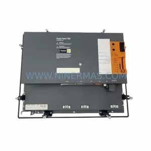
SKU: 5PP520.1043-00
B&R 5PP520.1043-00 Retrofit Power Panel for Legacy Systems
SKU: IRB7600 3HAC17484-1 3HAC062339-006 IRB6620 3HAC025007-001 DSQC1018 3HAC050363-001 DSQC1000 3HAC042766-001
ABB 3HAC17484-1 Service-Ready Spare for Industrial Maintenance
SKU: 6SE7023-4TC84-1HF3
Siemens 6SE7023-4TC84-1HF3 Service-Ready Industrial Spare