Original Industrial Spare Part
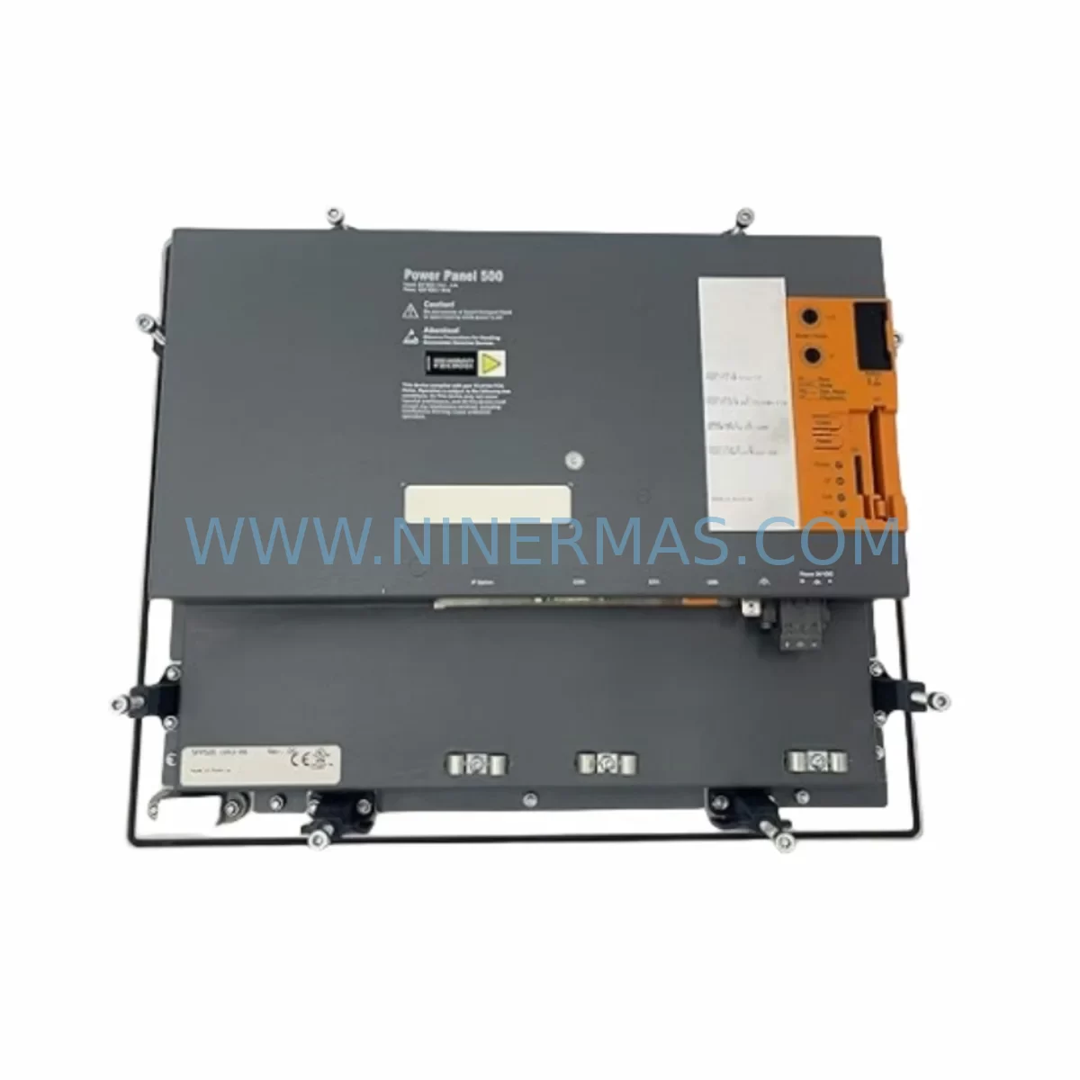
B&R 5PP520.1043-00 Retrofit Power Panel for Legacy Systems
Verify the part, confirm the platform family, and move straight into quotation with the right commercial details.
RFQ Ready
- SKU5PP520.1043-00
- CategoryPLC & Industrial Automation Modules
- BrandB&R
- SupportAvailability, lead time, condition, and shipping coordination
How Buyers Usually Use This Page
- Confirm the exact part number and platform family before sending the quote request.
- Use direct email when quantity, condition, and destination are already defined internally.
- Switch to the broader brand or category archive when you need alternates nearby.
Series Navigation
Move through the most common platform families behind this part.
Product RFQ
Send this part directly for quotation.
Include quantity, required condition, destination country, and target delivery timing. Current reference: B&R 5PP520.1043-00 Retrofit Power Panel for Legacy Systems with SKU 5PP520.1043-00.
B&R 5PP520.1043-00 Retrofit Power Panel for Legacy Systems
The B&R 5PP520.1043-00 is a compact, high-performance Power Panel HMI unit from B&R Automation’s PP500 series, designed for integrated operator control and visualization in industrial automation environments. As legacy B&R Power Panel installations approach end-of-life, the 5PP520.1043-00 serves as a proven retrofit-compatible replacement for discontinued PP200 and PP300 series panels, enabling plant engineers to modernize control cabinet interfaces without redesigning the underlying PLC architecture or rewriting core program logic.
NINERMAS maintains verified stock of the 5PP520.1043-00 with full pre-shipment functional testing and a 12-month warranty, supporting maintenance teams that require fast, reliable spare parts supply for critical production lines.
Upgrade Compatibility Table
| Parameter | Details |
|---|---|
| SKU / Part Number | 5PP520.1043-00 |
| Series | B&R PP500 Power Panel |
| Display | 10.4″ TFT Color LCD |
| Interface / Connectivity | USB, CF Card Slot, Ethernet (POWERLINK / standard) |
| Backplane / Rack Compatibility | Compatible with B&R X20 and X67 system backplanes via integrated controller interface |
| Communication Protocols | POWERLINK, Modbus TCP, CANopen (firmware-dependent) |
| Typical Replacement Targets | B&R 4PP220, 4PP320, 4PP420 series panels; legacy PP200/PP300 HMI units |
| Power Supply Requirement | 24 VDC nominal; verify existing cabinet PSU capacity before installation |
| Mounting / Installation Space | Panel-cut mounting; confirm cutout dimensions against existing cabinet door |
| Programming Environment | B&R Automation Studio 4.x; verify project target version compatibility |
| HMI Screen Migration | Existing VC4 / mapp View visualization projects require target hardware re-mapping |
| Warranty | 12 Months — NINERMAS Company Limited |
| Pre-Shipment Testing | Full functional test performed on every unit |
| Availability | In Stock — Ready to Ship |
Retrofit Planning for Existing Automation Systems
Replacing a legacy B&R Power Panel in an active production environment requires careful pre-migration planning across multiple system layers. When integrating the 5PP520.1043-00 into an existing control cabinet, engineers should begin by auditing the 24 VDC power supply module — such as a B&R 0PS1100.1 or equivalent — to confirm it can sustain the additional current draw of the new panel alongside co-installed X20 I/O modules and communication cards.
Terminal wiring from the legacy panel’s I/O interface must be mapped against the 5PP520.1043-00’s connector layout. In many PP200-era installations, signal wiring was routed through a dedicated X20 terminal block adapter or a third-party signal isolator; these intermediate components should be retained or replaced with compatible equivalents to avoid signal integrity issues during commissioning. Where analog input channels are involved, verify that existing X20AI4622 or similar analog input modules remain within the address range expected by the migrated PLC program.
For systems running B&R POWERLINK as the field bus backbone, the 5PP520.1043-00’s integrated POWERLINK interface must be assigned the correct node address to match the existing network topology. If the legacy panel was also acting as a POWERLINK Managing Node, the new unit’s firmware and Automation Studio project must be configured accordingly — a task that typically requires a B&R programming cable (USB or Ethernet) and access to the original .apj project archive.
Where the control system includes a B&R X20CP1586 or similar compact CPU module mounted on an X20 backplane, the 5PP520.1043-00 can be connected via Ethernet to serve as the operator interface without disrupting the CPU’s scan cycle. This architecture is common in retrofit projects where the original panel was a standalone HMI with no embedded controller, and the PLC logic resides entirely on a separate CPU rack.
In larger control cabinets that also house X20DO9322 digital output modules, X20DI9371 digital input modules, and a B&R X20BM11 bus module, the physical installation of the 5PP520.1043-00 should be planned around available panel-door cutout space. Older cabinets designed for 4PP220 or 4PP320 panels may require a cutout adapter plate to accommodate the 5PP520’s bezel dimensions. Confirm all measurements before ordering to avoid on-site rework.
For facilities running mixed communication environments — for example, a legacy Modbus RTU network alongside a newer POWERLINK segment — the 5PP520.1043-00 supports protocol bridging through Automation Studio’s communication object configuration. This eliminates the need for a standalone protocol converter in many upgrade scenarios, reducing both component count and potential failure points in the modernized control architecture.
Downtime Control During System Migration
Minimizing unplanned downtime is the primary concern in any spare parts replacement or control system retrofit. When replacing a failed or end-of-life B&R Power Panel with the 5PP520.1043-00, the recommended approach is to pre-configure the replacement unit offline — loading the Automation Studio project, mapping I/O addresses, and validating HMI screen assignments — before the scheduled maintenance window begins.
The original PLC program logic stored on the CPU module (such as a B&R X20CP3586 or X20CP1586) is not affected by swapping the operator panel, provided the panel is not acting as the program host. This means that in most retrofit scenarios, the underlying ladder logic, function block diagrams, and safety interlocks remain intact and operational throughout the panel replacement process, significantly reducing the risk of inadvertent program loss.
Field teams should prepare a pre-migration checklist that includes: backing up the current Automation Studio project to a CF card or network share; photographing all terminal wiring before disconnection; recording the POWERLINK node address and IP configuration of the existing panel; and confirming that the replacement 5PP520.1043-00 has been pre-loaded with the correct firmware version. With this preparation complete, physical swap time on a well-documented system can typically be reduced to under two hours, keeping production interruption within a single planned shift.
Post-installation, a structured commissioning sequence — powering up the panel, verifying POWERLINK link status LEDs, confirming I/O module recognition in Automation Studio’s online view, and running a full HMI screen navigation test — ensures that the system is returned to normal operation with full confidence before the maintenance window closes.
Retrofit Support FAQ
Q1: Is the 5PP520.1043-00 a direct drop-in replacement for the 4PP220 or 4PP320 series panels?
The 5PP520.1043-00 is functionally compatible as an HMI replacement for legacy 4PP220 and 4PP320 units in most applications, but it is not a mechanical drop-in — panel cutout dimensions differ between generations. An adapter plate or cabinet door modification is typically required. The Automation Studio project must also be re-targeted to the 5PP520 hardware configuration before deployment.
Q2: What commissioning steps are required after installing the 5PP520.1043-00?
After physical installation and wiring, connect the panel to the Automation Studio development PC via USB or Ethernet programming cable. Transfer the pre-configured project, verify POWERLINK node address assignment, confirm all X20 I/O modules are recognized online, and perform a full HMI screen functional test. Document all IP and node address settings for future maintenance reference.
Q3: Does NINERMAS provide pre-shipment testing and warranty coverage?
Yes. Every 5PP520.1043-00 unit shipped by NINERMAS undergoes full functional testing prior to dispatch. All units are covered by a 12-month warranty from the date of shipment. In the event of a warranty claim, NINERMAS provides direct technical support and replacement coordination to minimize impact on your production schedule.
Q4: What is the typical lead time and stock availability for the 5PP520.1043-00?
NINERMAS maintains ready stock of the 5PP520.1043-00 to support urgent maintenance and retrofit requirements. Standard orders are processed and dispatched within 1–3 business days. For large-quantity or long-term supply agreements, contact our sales team to discuss inventory reservation and scheduled delivery arrangements.
| Product Series | Legacy |
|---|---|
| Country of Origin | AT |
Catalog Continuation
More B&R modules in the catalog.
Use the brand lane to compare nearby part numbers, platform-adjacent modules, and other inquiry-ready listings before sending your final RFQ.
SKU: 4PP220.0571-45
B&R 4PP220.0571-45 Retrofit-Compatible Panel for Legacy Systems
SKU: 4PP045.0571-062
B&R 4PP045.0571-062 Retrofit-Compatible Panel for Legacy Systems
Catalog Continuation
Alternative parts within PLC & Industrial Automation Modules.
Stay inside the same system family when you need substitutes, adjacent modules, or a broader shortlist for procurement review.
SKU: 531X133PRUALG1
GE 531X133PRUALG1 Retrofit-Compatible Process Interface Board
SKU: IRB7600 3HAC17484-1 3HAC062339-006 IRB6620 3HAC025007-001 DSQC1018 3HAC050363-001 DSQC1000 3HAC042766-001
ABB 3HAC17484-1 Service-Ready Spare for Industrial Maintenance
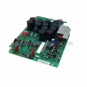
SKU: 6SE7023-4TC84-1HF3
Siemens 6SE7023-4TC84-1HF3 Service-Ready Industrial Spare