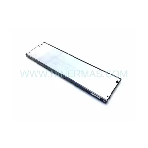
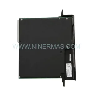
Original Industrial Spare Part
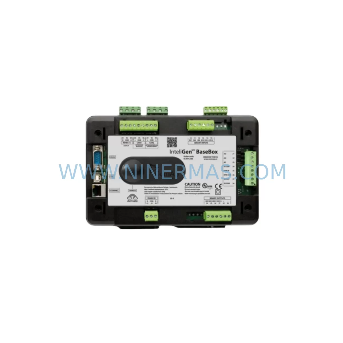
ComAp IG-NTC HW 1.3-TO Retrofit Gen-Set Controller
Verify the part, confirm the platform family, and move straight into quotation with the right commercial details.
RFQ Ready
- SKUGen-Set Controller InteliGen IG-NTC HW version 1.3-TO
- CategoryPLC & Industrial Automation Modules
- BrandComAp
- SupportAvailability, lead time, condition, and shipping coordination
How Buyers Usually Use This Page
- Confirm the exact part number and platform family before sending the quote request.
- Use direct email when quantity, condition, and destination are already defined internally.
- Switch to the broader brand or category archive when you need alternates nearby.
Series Navigation
Move through the most common platform families behind this part.
Product RFQ
Send this part directly for quotation.
Include quantity, required condition, destination country, and target delivery timing. Current reference: ComAp IG-NTC HW 1.3-TO Retrofit Gen-Set Controller with SKU Gen-Set Controller InteliGen IG-NTC HW version 1.3-TO.
ComAp IG-NTC HW 1.3-TO Retrofit-Compatible Gen-Set Controller for Legacy Systems
The ComAp IG-NTC HW 1.3-TO is a ruggedized genset control module from ComAp’s InteliGen (IG) series, engineered for demanding generator set applications in industrial, telecom, and critical power environments. As legacy control panels age and original spare parts become increasingly difficult to source, the IG-NTC HW 1.3-TO remains one of the most sought-after retrofit-compatible controllers for operators maintaining older ComAp-based generator installations. This unit supports direct replacement of earlier IG-NTC hardware revisions and integrates seamlessly into existing InteliGen control architectures without requiring full panel redesign.
Whether you are managing a fleet of standby generators at a data center, replacing a failed controller on a prime-power diesel set at a remote mining site, or upgrading a legacy automatic mains failure (AMF) panel, the IG-NTC HW 1.3-TO provides the control logic, communication interfaces, and environmental resilience required for continuous operation. Its ruggedized design addresses the thermal cycling, vibration, and humidity exposure common in generator enclosures, making it a reliable long-term replacement for worn or obsolete control hardware.
Upgrade Compatibility Table
| Parameter | IG-NTC HW 1.3-TO (This Unit) | Retrofit Notes |
|---|---|---|
| Hardware Revision | HW 1.3-TO (Ruggedized) | Compatible with IG-NTC HW 1.x panel wiring; verify terminal mapping against site drawings |
| Communication Interface | RS-232 / RS-485 (Modbus RTU) | Confirm baud rate and address settings match existing SCADA or BMS configuration |
| Power Supply Input | 8–36 V DC (battery-backed) | Verify panel battery charger output; check for voltage drop under cranking conditions |
| Mounting / Form Factor | Panel-mount, DIN-compatible cutout | Confirm cutout dimensions match existing panel aperture; no mechanical modification typically required for same-series replacement |
| I/O Configuration | Digital inputs/outputs, analog inputs | Re-map I/O assignments in InteliConfig if replacing a different HW sub-revision; backup original configuration file before replacement |
| Firmware Compatibility | Supports InteliGen firmware stack | Load matching firmware version via InteliConfig; retain original .cfg archive for rollback |
| Display / HMI | Integrated LCD with keypad | Existing operator interface screens remain valid; verify alarm text mapping after firmware upload |
| Replacement Scope | Direct drop-in for IG-NTC HW 1.x series | May also replace IG-NT or IG-NTC variants with wiring adaptation; consult ComAp migration guide |
| Warranty | 12-Month Warranty | Pre-Shipment Tested | In-Stock Supply | |
Retrofit Planning for Existing Automation Systems
Replacing a genset controller in an operational facility requires careful coordination across multiple system layers. The IG-NTC HW 1.3-TO is typically installed within a generator control panel alongside a range of supporting components, and a successful retrofit depends on verifying compatibility at each interface point before the old unit is removed.
Begin with the power supply architecture. The IG-NTC HW 1.3-TO operates from the generator’s starting battery bank, typically 12 V or 24 V DC. Before replacement, confirm that the existing battery charger module — often a ComAp InteliCharger or equivalent third-party unit — delivers stable voltage within the controller’s input range under both standby and cranking load conditions. Voltage sag during engine start is a common cause of controller reset faults in legacy panels and should be measured with a data logger prior to commissioning the replacement unit.
Terminal wiring is the next critical checkpoint. The IG-NTC HW 1.3-TO uses a defined terminal block layout for engine control signals including start relay output, fuel solenoid output, oil pressure input, coolant temperature input, and generator voltage/current sensing. When migrating from an earlier IG-NTC hardware revision, the terminal assignments are generally preserved, but field engineers should cross-reference the site wiring diagram against the HW 1.3-TO terminal specification sheet. Pay particular attention to the magnetic pickup (MPU) input for engine speed sensing, as signal conditioning requirements may differ between hardware sub-revisions.
The backplane and module addressing context is equally important for sites running expanded InteliGen architectures. In multi-module panels where the IG-NTC HW 1.3-TO communicates with expansion I/O modules such as the ComAp IG-IOM (I/O module) or interfaces with a ComAp IG-EXT extension module, the CAN bus address and module ID settings must be preserved or reconfigured to match the original panel topology. Failure to replicate the module address map will result in communication faults and may prevent the controller from recognizing attached I/O or protection relay modules.
For sites with SCADA or building management system (BMS) integration, the RS-485 Modbus RTU link between the IG-NTC HW 1.3-TO and the upstream supervisory system must be re-established after replacement. Confirm the Modbus device address, baud rate (typically 9600 or 19200 bps), parity, and stop bit settings in the controller’s communication configuration. If the site uses a ComAp WebSupervisor or a third-party SCADA platform, verify that the register map used by the supervisory system matches the firmware version loaded on the replacement controller. In some cases, a firmware delta between the original and replacement unit may shift register addresses for key parameters such as engine run hours, load percentage, and alarm status words.
HMI screen validation is a step that is frequently underestimated during genset controller retrofits. After the IG-NTC HW 1.3-TO is installed and the configuration file is loaded, walk through all operator display screens to confirm that setpoint labels, alarm descriptions, and measurement units are correctly rendered. If the panel also includes a remote annunciator panel or a ComAp InteliVision display connected via the controller’s communication port, verify that the display firmware is compatible with the controller firmware version in use.
Installation space confirmation is straightforward for same-series replacements but should not be skipped. Measure the panel cutout and confirm that the IG-NTC HW 1.3-TO’s bezel dimensions and mounting clip positions match the existing aperture. In older panels where the cutout was made for an earlier IG-NT or IG-NTC variant, minor dimensional differences may require a panel adapter plate. Also confirm that adequate clearance exists behind the panel for the controller’s connector harness and any communication cables routed to the RS-232 or RS-485 ports.
Finally, document the pre-replacement configuration by extracting the full configuration archive from the original controller using InteliConfig software before powering down the panel. This archive serves as the baseline for programming the replacement unit and provides a rollback reference if commissioning issues arise. Archive the .cfg file, firmware version string, and a photograph of the terminal wiring before disconnection.
Downtime Control During System Migration
Minimizing generator downtime during a controller replacement is a primary concern for facilities where the generator set provides standby or prime power to critical loads. A structured replacement procedure for the IG-NTC HW 1.3-TO can typically be completed within a planned maintenance window of two to four hours, depending on panel complexity and the extent of I/O re-mapping required.
The most effective downtime reduction strategy is pre-programming. Before the maintenance window begins, use InteliConfig to load the archived configuration file onto the replacement IG-NTC HW 1.3-TO on a bench setup. Verify that the controller powers up correctly, accepts the configuration without errors, and displays the expected setpoints and I/O assignments. This bench verification step eliminates the most common source of extended downtime — discovering configuration errors after the panel has been de-energized and the original controller removed.
During the replacement window, follow a defined sequence: isolate the generator from the load bus, de-energize the control panel, photograph and label all terminal connections, remove the original controller, install the pre-programmed replacement unit, reconnect terminals in sequence, restore panel power, and perform a no-load functional test before returning the generator to automatic standby mode. This sequence protects the original program logic by ensuring the replacement unit is already configured before any field wiring is disturbed.
For sites where continuous generator availability is mandatory, consider staging a temporary bypass using a portable generator or UPS extension to maintain critical loads during the controller swap. This approach is particularly relevant in data center, hospital, and telecommunications applications where even a brief loss of standby coverage is unacceptable. Coordinate with the facility’s electrical team to confirm load transfer procedures and ensure that the temporary power source is rated for the critical load profile.
After installation, perform a full automatic test cycle: simulate a mains failure, confirm that the IG-NTC HW 1.3-TO initiates the start sequence correctly, verify load transfer timing, confirm alarm and protection relay responses, and test the remote communication link to the SCADA or BMS system. Document the test results and retain them as part of the panel maintenance record. This commissioning record also supports warranty claims and provides evidence of correct installation for insurance and compliance purposes.
Retrofit Support FAQ
Q: Is the IG-NTC HW 1.3-TO a direct replacement for earlier IG-NTC hardware revisions?
A: In most cases, yes. The HW 1.3-TO shares the same panel cutout dimensions, terminal block layout, and communication interface as earlier IG-NTC revisions. However, always cross-reference the terminal wiring diagram and verify firmware compatibility using InteliConfig before installation. Minor I/O re-mapping may be required if replacing a significantly older sub-revision.
Q: What commissioning steps are required after installing the replacement controller?
A: Load the archived configuration file via InteliConfig, verify all I/O assignments and setpoints, confirm communication link parameters (Modbus address, baud rate), perform a no-load start test, and execute a full automatic mains failure simulation. Document all test results before returning the generator to service.
Q: Does this unit ship pre-tested, and what warranty is provided?
A: Yes. Every IG-NTC HW 1.3-TO unit is pre-shipment tested to verify power-up, I/O functionality, and communication interface operation before dispatch. A 12-month warranty is included, covering manufacturing defects under normal operating conditions. Units are dispatched from in-stock inventory to minimize lead time for urgent replacement requirements.
Q: Can this controller be used to replace a ComAp IG-NT or IG-NTC variant from a different sub-series?
A: Cross-variant replacement is possible in many cases but requires additional verification. Differences in terminal assignments, I/O count, and firmware feature sets between IG-NT and IG-NTC sub-series may require wiring adaptation and configuration adjustments. Contact our technical team with your original controller part number and panel wiring diagram for a pre-sale compatibility assessment before ordering.
| Product Series | Other series |
|---|
Catalog Continuation
More ComAp modules in the catalog.
Use the brand lane to compare nearby part numbers, platform-adjacent modules, and other inquiry-ready listings before sending your final RFQ.
SKU: Gen-Set Controller InteliGen IG-NTGC HW version 1.3-TO
ComAp IG-NTGC HW 1.3-TO Safety-Reliable Gen-Set Controller
Catalog Continuation
Alternative parts within PLC & Industrial Automation Modules.
Stay inside the same system family when you need substitutes, adjacent modules, or a broader shortlist for procurement review.