Original Industrial Spare Part
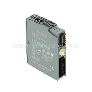
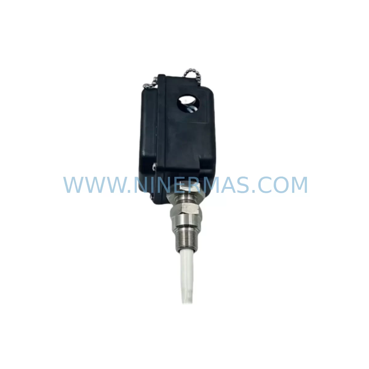
Bently Nevada 330881-16-08-095-06-02 Retrofit-Compatible Proximity Transducer
Verify the part, confirm the platform family, and move straight into quotation with the right commercial details.
RFQ Ready
- SKU330881-16-08-095-06-02
- CategoryTSI & Rotating Machinery Monitoring
- BrandBently Nevada
- SupportAvailability, lead time, condition, and shipping coordination
How Buyers Usually Use This Page
- Confirm the exact part number and platform family before sending the quote request.
- Use direct email when quantity, condition, and destination are already defined internally.
- Switch to the broader brand or category archive when you need alternates nearby.
Series Navigation
Move through the most common platform families behind this part.
Product RFQ
Send this part directly for quotation.
Include quantity, required condition, destination country, and target delivery timing. Current reference: Bently Nevada 330881-16-08-095-06-02 Retrofit-Compatible Proximity Transducer with SKU 330881-16-08-095-06-02.
Bently Nevada 330881-16-08-095-06-02 Retrofit-Compatible Proximity Transducer for Legacy PROXPAC XL Systems
The Bently Nevada 330881-16-08-095-06-02 is a high-precision eddy-current proximity transducer engineered for the PROXPAC XL series vibration monitoring platform. As aging distributed control systems and machinery protection networks approach end-of-life, this module has become one of the most sought-after retrofit components for facilities seeking to extend the operational lifespan of their existing Bently Nevada 3300 and 3500 series infrastructure without committing to a full platform migration. Whether you are managing a turbine protection panel, a compressor monitoring rack, or a rotating machinery control cabinet, the 330881-16-08-095-06-02 provides a verified drop-in upgrade path that preserves your existing wiring topology, signal conditioning chain, and alarm logic.
In legacy automation environments, the challenge of replacing discontinued proximity transducers goes far beyond sourcing the part. Engineers must verify power supply compatibility — typically ±24 VDC from a dedicated Bently Nevada power conditioner such as the 3300/20 or 3300/25 — and confirm that the existing barrier or driver module, often a 3300 XL 8mm or 3300 XL 11mm proximitor, remains within calibrated range for the new transducer’s gap voltage output. The 330881-16-08-095-06-02 operates within the standard Bently Nevada voltage output window of -2 VDC to -18 VDC, making it directly compatible with most installed 3500/42M and 3500/45 monitor cards without requiring recalibration of the full channel.
Terminal wiring during retrofit must be carefully managed. The transducer uses a standard coaxial extension cable interface — typically mating with an 330130 or 330180 series extension cable — and the field connector pinout must be verified against the existing junction box or terminal strip layout before installation. In many older installations, the cable routing passes through conduit shared with other signal lines, and maintaining proper shielding continuity is critical to avoiding ground loop interference that can trigger false vibration alarms on adjacent channels of the 3500 rack.
Upgrade Compatibility Table
| Parameter | 330881-16-08-095-06-02 (This Unit) | Legacy / Replaced Models |
|---|---|---|
| Series | PROXPAC XL | PROXPAC, 3300 XL |
| Probe Diameter | 8 mm | 8 mm (compatible) |
| Cable Length | 0.9 m (3 ft) | Varies — verify extension cable |
| Supply Voltage | -24 VDC (nominal) | -24 VDC (compatible) |
| Output Range | -2 VDC to -18 VDC | -2 VDC to -18 VDC (compatible) |
| Monitor Compatibility | 3500/42M, 3500/45, 3500/46M | 3300/16, 3300/20 (verify firmware) |
| Extension Cable Interface | 330130 / 330180 series | Confirm existing cable part number |
| Installation Space | Standard probe boss mount | Same — no mechanical modification required |
| Communication Protocol | Analog (4–20 mA / voltage) | Analog (compatible) |
| Commissioning Requirement | Gap voltage verification, channel calibration check | Full recalibration if replacing older 3300 series |
| Warranty | 12 Months — NINERMAS COMPANY LIMITED | |
Retrofit Planning for Existing Automation Systems
Successful integration of the 330881-16-08-095-06-02 into a running plant begins with a thorough pre-outage audit. Maintenance teams should document the current gap voltage reading at the proximitor output — typically measured at the 3500 rack’s I/O module terminal block — and record the baseline vibration and position readings from the 3500 operator display or the connected DCS historian. This baseline becomes the acceptance criterion for post-installation commissioning.
The retrofit process typically involves the following sequence: isolate the affected channel on the 3500/42M or 3500/45 monitor card by placing it in bypass mode via the rack’s keyswitch or through the System 1 software interface; disconnect the existing coaxial cable at the junction box; install the 330881-16-08-095-06-02 at the probe boss, verifying thread engagement and tip clearance against the target shaft; reconnect the 330130 extension cable and verify continuity and shield integrity; restore power to the proximitor driver and measure gap voltage at the terminal strip to confirm the reading falls within the -10 VDC ±1 VDC nominal operating window for a standard 1.0 mm gap.
In multi-channel protection racks, it is common to find that adjacent channels share a common power conditioner — such as the 3300/25 dual-output power supply — and any voltage sag during the replacement procedure can affect live channels monitoring critical machinery. Coordinating the outage window with the operations team and pre-staging a spare 3300/25 or equivalent power module in the control cabinet significantly reduces this risk.
For facilities migrating from older 3300 series monitors to the 3500 platform, the 330881-16-08-095-06-02 is fully compatible with the 3500 rack’s I/O module architecture. However, engineers should verify that the 3500/20 rack interface module firmware supports the channel configuration required for the new transducer, and that the System 1 software database has been updated to reflect the new probe serial number and calibration coefficients. HMI screens connected to the 3500 rack via Modbus TCP or OPC-DA should be reviewed to confirm that the tag mapping for the replaced channel remains intact after the configuration update.
Where I/O expansion is part of the broader upgrade scope, the 3500/40M eight-channel monitor or the 3500/50 tachometer input module may be added to the same rack to accommodate additional measurement points without requiring a separate control cabinet. Signal isolators — such as the MTL 5541 or equivalent DIN-rail-mounted barrier — should be considered for any channel where the cable run exceeds 30 metres or passes through areas with high electromagnetic interference from variable frequency drives or large motor starters.
Downtime Control During System Migration
Minimizing unplanned downtime during a proximity transducer replacement requires careful pre-staging and a disciplined change management process. NINERMAS recommends the following approach for facilities operating continuous processes where machinery protection cannot be fully bypassed for extended periods.
First, perform a hot-standby verification: confirm that the 330881-16-08-095-06-02 has been bench-tested against a reference proximitor driver before it arrives on site. Each unit shipped by NINERMAS undergoes an outgoing quality check that verifies gap voltage linearity across the full measurement range, connector integrity, and cable continuity. The 12-month warranty covers any failure attributable to manufacturing defects discovered during this commissioning phase.
Second, prepare a channel bypass procedure in advance. On the 3500 platform, individual channels can be placed in bypass without affecting adjacent channels or triggering a rack-level fault. Document the bypass sequence, the expected alarm state changes in the DCS, and the notification protocol for the control room operator before the work begins. This preparation alone can reduce the active outage window from several hours to under 30 minutes for a single-channel replacement.
Third, protect the existing program logic. If the 3500 rack is connected to a safety instrumented system or a PLC-based interlock — such as a Rockwell Automation ControlLogix or Siemens S7-300 — confirm with the control systems engineer that the bypass state of the vibration channel will not inadvertently satisfy a permissive condition or mask a genuine process alarm. Retain a backup of the 3500 rack configuration file from System 1 before making any changes, and verify the restore procedure has been tested in a non-production environment.
Finally, schedule the physical installation during a planned maintenance window aligned with the machinery’s normal inspection interval. This approach allows the replacement of the 330881-16-08-095-06-02 to be combined with other scheduled tasks — such as bearing inspection, coupling alignment, or lube oil system maintenance — maximizing the value of each outage and keeping the overall annual downtime budget within target.
Retrofit Support FAQ
Q1: Is the 330881-16-08-095-06-02 a direct drop-in replacement for older PROXPAC and 3300 XL series proximity transducers?
A: In most installations, yes. The 330881-16-08-095-06-02 shares the same 8 mm probe diameter, coaxial cable interface, and output voltage range as the standard PROXPAC XL family. However, customers should verify the extension cable part number — particularly whether the existing installation uses a 330130 or 330180 series cable — and confirm that the proximitor driver’s scale factor matches the new transducer’s sensitivity specification before finalizing the replacement order.
Q2: What commissioning steps are required after installation?
A: After physical installation, measure the gap voltage at the proximitor output terminal with the shaft stationary at the nominal operating gap. The reading should fall within -10 VDC ±1 VDC for a 1.0 mm gap. If the reading is outside this range, adjust the probe position and re-measure. Once the gap voltage is confirmed, remove the channel bypass on the 3500 monitor, verify that the vibration and position readings displayed in System 1 or the DCS match the pre-outage baseline, and document the as-left calibration data in the maintenance management system.
Q3: Does NINERMAS provide stock availability and fast delivery for the 330881-16-08-095-06-02?
A: Yes. NINERMAS maintains inventory of the 330881-16-08-095-06-02 and related PROXPAC XL components to support urgent replacement requirements. Standard lead time for in-stock units is 3–7 business days for international shipments. Each unit is shipped with an outgoing test report and is covered by a 12-month warranty from the date of delivery. Contact sale@ninermas.com or call +0086 187 5021 5667 for real-time stock confirmation and expedited shipping options.
Q4: What should I check if the replacement transducer triggers a high-vibration alarm immediately after installation?
A: The most common causes are an incorrect gap setting (probe tip too close or too far from the shaft), a damaged or improperly shielded extension cable introducing noise into the signal, or a scale factor mismatch between the new transducer and the existing proximitor driver configuration in the 3500 monitor. Check the gap voltage first, then inspect the cable shield continuity, and finally review the channel configuration in System 1 to confirm the sensitivity and scale factor parameters match the 330881-16-08-095-06-02 specification sheet.
| Product Series | 3308 |
|---|---|
| Country of Origin | US |
Catalog Continuation
More Bently Nevada modules in the catalog.
Use the brand lane to compare nearby part numbers, platform-adjacent modules, and other inquiry-ready listings before sending your final RFQ.
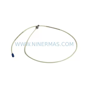
SKU: 21504-000-016-05-02
Bently Nevada 21504-000-016-05-02 Safety Proximity Probe
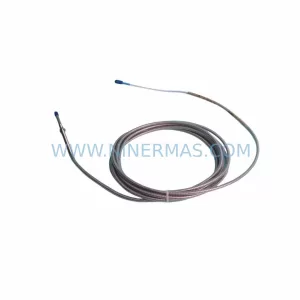
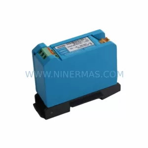
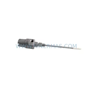
SKU: 21000-16-05-25-020-04-02
Bently Nevada 21000-16-05-25-020-04-02 Retrofit-Compatible Proximitor for Legacy Systems
Catalog Continuation
Alternative parts within TSI & Rotating Machinery Monitoring.
Stay inside the same system family when you need substitutes, adjacent modules, or a broader shortlist for procurement review.
SKU: 21000-16-10-00-103-04-02
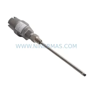
Bently Nevada 21000-16-10-00-103-04-02 Service-Ready Spare Part
SKU: 330905-00-06-10-01-00
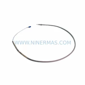
Bently Nevada 330905-00-06-10-01-00 Safety-Reliable Proximity Transducer
SKU: 330881-28-00-050-03-02
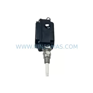
Bently Nevada 330881-28-00-050-03-02 Service-Ready Spare Part