Original Industrial Spare Part
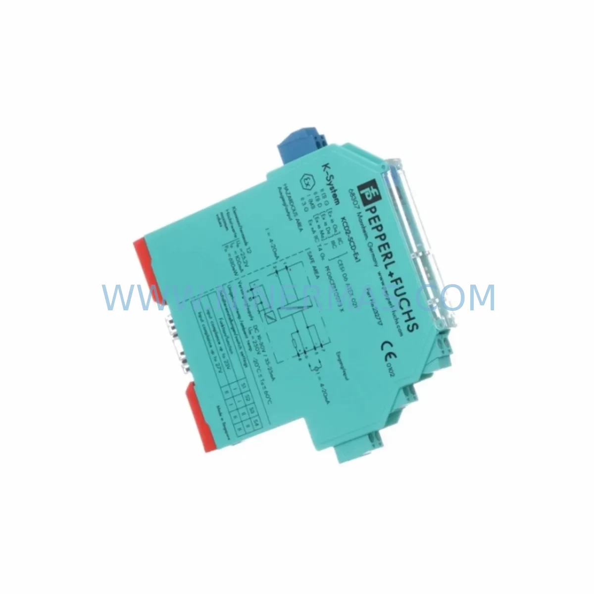
Pepperl+Fuchs KCD2-SCD-EX1 Service-Ready Industrial Spare Part
Verify the part, confirm the platform family, and move straight into quotation with the right commercial details.
RFQ Ready
- SKUKCD2-SCD-EX1 KCD2-STC-EX1
- CategorySIS Safety & Redundancy Systems
- BrandPepperl+Fuchs
- SupportAvailability, lead time, condition, and shipping coordination
How Buyers Usually Use This Page
- Confirm the exact part number and platform family before sending the quote request.
- Use direct email when quantity, condition, and destination are already defined internally.
- Switch to the broader brand or category archive when you need alternates nearby.
Series Navigation
Move through the most common platform families behind this part.
Product RFQ
Send this part directly for quotation.
Include quantity, required condition, destination country, and target delivery timing. Current reference: Pepperl+Fuchs KCD2-SCD-EX1 Service-Ready Industrial Spare Part with SKU KCD2-SCD-EX1 KCD2-STC-EX1.
Pepperl+Fuchs KCD2-SCD-EX1 Service-Ready Industrial Spare Part
The Pepperl+Fuchs KCD2-SCD-EX1 is a K-System intrinsically safe signal conditioner designed for use in hazardous area installations across process automation, chemical, oil & gas, and pharmaceutical industries. As a service-ready spare part, the KCD2-SCD-EX1 is stocked, pre-tested, and available for immediate dispatch to support emergency replacement, planned maintenance, and annual shutdown schedules. Unplanned downtime caused by a failed signal conditioner in a critical measurement loop can cascade into production loss, safety incidents, and regulatory non-compliance. Maintaining a verified spare of the KCD2-SCD-EX1 in your control room inventory is a fundamental risk mitigation strategy for any facility operating Pepperl+Fuchs K-System barriers.
The KCD2-SCD-EX1 accepts a 4–20 mA input signal from field transmitters located in Zone 0, Zone 1, or Zone 2 hazardous areas and provides a galvanically isolated, conditioned output to the safe-side DCS or PLC. Its compact DIN-rail mounting format, wide supply voltage tolerance, and compatibility with the KCD2 power rail make it a versatile replacement component across a broad range of legacy and current-generation control cabinet configurations.
Spare Maintenance Table
| Parameter | Specification |
|---|---|
| Model | KCD2-SCD-EX1 |
| Companion Model | KCD2-STC-EX1 |
| Series | K-System (KCD2) |
| Brand | Pepperl+Fuchs |
| Function | Intrinsically Safe Signal Conditioner / Isolating Barrier |
| Input | 4–20 mA (HART compatible) |
| Output | 4–20 mA, galvanically isolated |
| Supply Voltage | 20–35 V DC via power rail or direct terminal |
| Hazardous Area Classification | Ex ia IIC / ATEX / IECEx certified |
| Mounting | DIN rail, 35 mm |
| Housing Width | 12.5 mm (single-width K-System module) |
| Operating Temperature | -20 °C to +60 °C |
| Degree of Protection | IP20 |
| Origin | Germany |
| Compatibility | KCD2 power rail, KFD2-series barriers, standard DCS/PLC analog input cards |
| Maintenance Recommendation | Inspect every 12 months; replace immediately upon loop error or output drift >0.5% |
| Warranty | 12 months from date of shipment |
| Pre-shipment Testing | Full functional and loop test performed before dispatch |
Maintenance Planning for Continuous Operation
When a KCD2-SCD-EX1 is identified as the fault source during a loop diagnostic, the replacement window is narrow — particularly in continuous process environments where the associated measurement point feeds a safety instrumented function or a critical control loop. Maintenance engineers should treat the KCD2-SCD-EX1 replacement as a trigger for a broader cabinet inspection rather than an isolated swap.
Begin by verifying the integrity of the KCD2 power rail supplying the module bank. A degraded power rail can cause intermittent supply voltage drops that stress multiple modules simultaneously, meaning the KCD2-SCD-EX1 failure may be a symptom rather than the root cause. Check the associated KFD0-CS-EX1 power supply module output voltage and ripple before reinstalling a new barrier.
Inspect the field-side wiring terminals and confirm that the cable screen is correctly terminated at the cabinet entry gland. Loose or corroded terminals on the field side are a common cause of 4–20 mA signal drift that is incorrectly attributed to barrier failure. Review the terminal blocks adjacent to the KCD2-SCD-EX1 — particularly any Phoenix Contact or Weidmüller DIN rail terminal blocks used for loop junction — for signs of oxidation or mechanical loosening.
If the loop includes HART communication for transmitter diagnostics or remote configuration, verify that the KFD2-HMM-16 HART multiplexer or equivalent HART interface module is still correctly polling the field device after the barrier replacement. HART signal integrity can be affected by changes in loop impedance introduced by a new module.
For installations where the KCD2-SCD-EX1 feeds a redundant analog input card, confirm that the DCS or PLC input channel — such as a Siemens ET 200SP AI module or equivalent — is reading correctly after the swap and that no latched fault alarms remain in the controller. Check the associated KCD2-STC-EX1 if it is installed in the same loop as a solenoid driver or switch amplifier, as both modules share the same power rail segment and a rail fault affects both simultaneously.
During annual shutdown maintenance, it is good practice to bench-test spare KCD2-SCD-EX1 units alongside related components including KFD2-SR2-EX1.W relay output modules, KCD2-UT2-EX1 universal transmitter power supplies, and KFD2-SCD-EX1 signal conditioners from the KFD2 series, which serve as functional equivalents in higher-density cabinet layouts. Maintaining a minimum of two spare units per installed base of ten is a widely adopted inventory strategy for K-System barriers in critical process plants.
Signal isolation integrity should also be verified using a loop calibrator after installation. If the facility uses Pepperl+Fuchs segment couplers for PROFIBUS PA or Foundation Fieldbus segments, confirm that the barrier replacement has not introduced ground loops that could affect fieldbus communication quality. A KFD2-CRG2-EX1.D charge amplifier or similar signal conditioning module in adjacent slots should be inspected for any indication of cross-talk or supply interference.
Fuse protection for the K-System power supply should be reviewed as part of the replacement workflow. Ensure that the KFD0-CS-EX1.1 or equivalent fuse module protecting the power rail segment is intact and rated correctly for the installed module count. An undersized or degraded fuse is a latent risk that can cause nuisance trips during peak load conditions.
Site Replacement Workflow
Step 1 — Isolation and Loop Identification: Identify the measurement loop associated with the failed KCD2-SCD-EX1 using the P&ID and cabinet layout drawing. Confirm the loop tag, the field transmitter model, and the DCS input channel address before proceeding. Place the associated control loop in manual mode at the DCS to prevent process upsets during the swap.
Step 2 — Safe Isolation: De-energize the power rail segment supplying the module or use the module’s individual terminal disconnection feature if available. Confirm that the field-side circuit is de-energized using an approved intrinsically safe loop tester before disconnecting field wiring.
Step 3 — Module Removal: Disconnect field wiring terminals (document terminal assignments before removal), release the DIN rail locking tab, and slide the KCD2-SCD-EX1 out of the power rail. Inspect the power rail connector pins for damage or contamination.
Step 4 — Replacement Installation: Slide the new KCD2-SCD-EX1 onto the power rail, ensuring full engagement of the power rail connector. Reconnect field wiring terminals per the documented terminal assignment. Verify that the module address or configuration switches (if applicable) match the removed unit.
Step 5 — Loop Verification: Re-energize the power rail segment. Apply a known 4–20 mA test signal from the field side using a loop calibrator and confirm that the output signal at the DCS input card matches within the specified accuracy. Return the control loop to automatic mode only after a stable reading is confirmed.
Step 6 — Documentation: Record the replacement in the maintenance management system (CMMS) with the module serial number, date of replacement, loop tag, and test results. Update the spare parts inventory to trigger a replenishment order for the consumed unit.
This workflow applies equally to the replacement of legacy Pepperl+Fuchs K-System barriers with current-production KCD2-SCD-EX1 units, ensuring backward compatibility and minimizing the risk of loop configuration errors during the transition.
Spare Parts Support FAQ
Q1: Is the KCD2-SCD-EX1 still in production, and can long-term supply be guaranteed?
The KCD2-SCD-EX1 remains an active Pepperl+Fuchs catalog item. NINERMAS maintains reserved inventory agreements to support long-term supply for customers with large installed bases. For facilities planning multi-year maintenance contracts, we recommend establishing a blanket order or reserved stock arrangement to protect against lead time variability. Contact our team to discuss long-term supply agreements.
Q2: How is the KCD2-SCD-EX1 tested before shipment?
Every unit dispatched by NINERMAS undergoes a full functional test including loop signal verification (4–20 mA input/output accuracy), power rail connector integrity check, and visual inspection for physical damage. A test report is available upon request. Units are shipped in anti-static packaging with individual serial number traceability.
Q3: Is the KCD2-SCD-EX1 compatible with my existing KCD2 power rail and cabinet layout?
Yes. The KCD2-SCD-EX1 is designed for direct plug-in compatibility with the standard KCD2 DIN rail power rail system. It is mechanically and electrically interchangeable with units from the same series. If you are replacing an older revision, confirm the ATEX/IECEx certificate revision with your safety engineer to ensure compliance with your site’s hazardous area documentation.
Q4: What does the 12-month warranty cover, and what is the claims process?
The 12-month warranty covers manufacturing defects and functional failures under normal operating conditions from the date of shipment. It does not cover damage caused by incorrect installation, overvoltage, or physical mishandling. To initiate a warranty claim, contact NINERMAS with the order reference, serial number, and a description of the fault. We will arrange return logistics and provide a replacement or repair within an agreed lead time.
| Product Series | Other series |
|---|---|
| Country of Origin | DE |
Catalog Continuation
More Pepperl+Fuchs modules in the catalog.
Use the brand lane to compare nearby part numbers, platform-adjacent modules, and other inquiry-ready listings before sending your final RFQ.
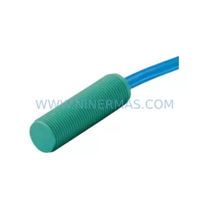
SKU: 0200X-ZE24-1011 80-S09/S10, 0190-18154 ABX-X302 722A11TGA3FC
P+F VAT-0200X-ZE24-1011-80-S09/S10 Safety-Reliable Valve Sensor
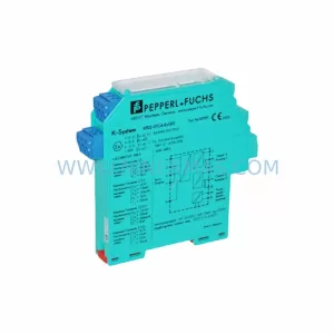
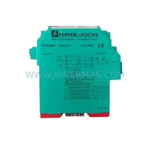
SKU: KFD2-STC4-EX1.2O
PEPPERL+FUCHS KFD2-STC4-EX1.2O Retrofit SMART Transmitter Power Supply
Catalog Continuation
Alternative parts within SIS Safety & Redundancy Systems.
Stay inside the same system family when you need substitutes, adjacent modules, or a broader shortlist for procurement review.
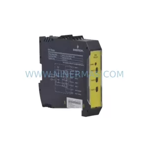
SKU: KJ3143X1-BA1 12P2830X022
Emerson KJ3143X1-BA1 Safety-Reliable Digital Input Module
SKU: 8C-IP0102 8C-TPOXA1 8C-TPOX01 51309550-275
Honeywell 8C-IP0102 Safety-Reliable I/O Link for Critical Sites
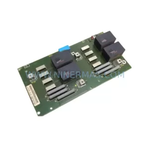
SKU: 6SE7024-7FD84-1HH0
SIEMENS 6SE7024-7FD84-1HH0 Safety-Reliable AC Drive