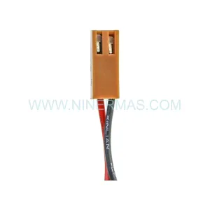
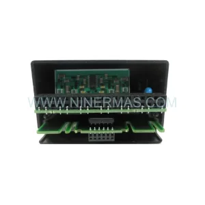
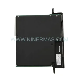
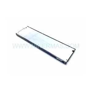
Original Industrial Spare Part
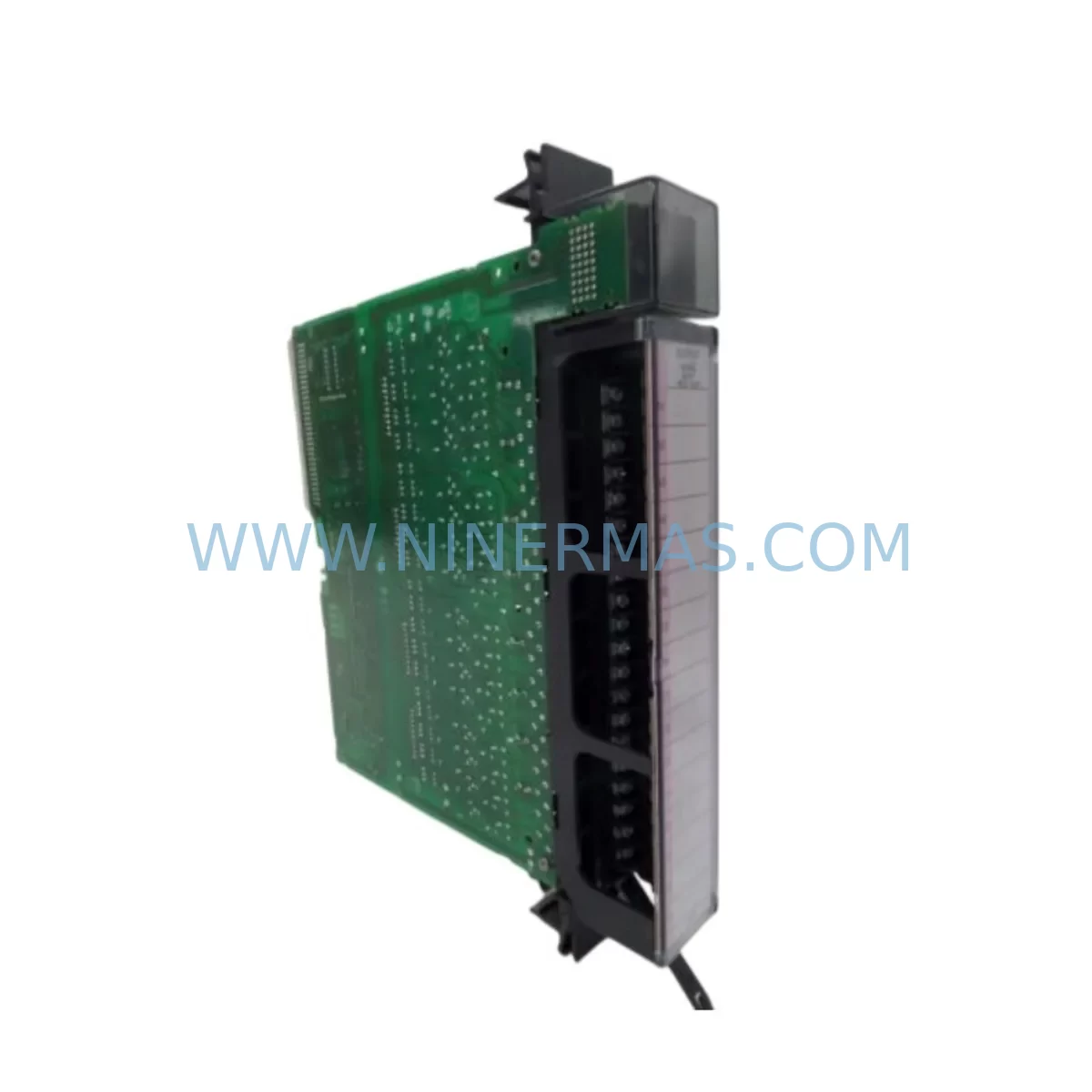
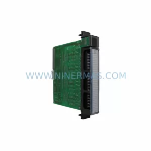
GE IC697MDL340 Retrofit-Compatible Output Module Legacy
Verify the part, confirm the platform family, and move straight into quotation with the right commercial details.
RFQ Ready
- SKUIC697MDL340
- CategoryPLC & Industrial Automation Modules
- BrandGE
- SupportAvailability, lead time, condition, and shipping coordination
How Buyers Usually Use This Page
- Confirm the exact part number and platform family before sending the quote request.
- Use direct email when quantity, condition, and destination are already defined internally.
- Switch to the broader brand or category archive when you need alternates nearby.
Series Navigation
Move through the most common platform families behind this part.
Product RFQ
Send this part directly for quotation.
Include quantity, required condition, destination country, and target delivery timing. Current reference: GE IC697MDL340 Retrofit-Compatible Output Module Legacy with SKU IC697MDL340.
GE IC697MDL340 Retrofit-Compatible Output Module for Legacy Series 90-70 Systems
The GE IC697MDL340 is a 32-point discrete output module designed for the GE Series 90-70 PLC platform. As production lines age and original spare parts become increasingly difficult to source, the IC697MDL340 remains one of the most sought-after retrofit components for engineers tasked with keeping legacy automation systems operational. Whether you are replacing a failed output module in an existing control cabinet, upgrading a discontinued I/O rack, or migrating from an end-of-life control architecture, the IC697MDL340 provides a direct, drop-in compatible solution that minimizes engineering rework and reduces unplanned downtime.
NINERMAS maintains verified stock of the IC697MDL340 with full functional testing prior to shipment. Each unit ships with a 12-month warranty covering manufacturing defects and operational failures under normal industrial use conditions.
Upgrade Compatibility Table
| Parameter | IC697MDL340 Specification | Retrofit Notes |
|---|---|---|
| Output Points | 32 discrete outputs | Verify field wiring terminal mapping before swap |
| Output Voltage | 12–48 VDC / 120 VAC | Confirm field device voltage compatibility |
| Rack Compatibility | IC697CHS750, IC697CHS782, IC697CHS790 | Slot position must match original module address |
| Backplane Interface | Series 90-70 VME-based backplane | Not compatible with Series 90-30 or PACSystems racks |
| Communication Protocol | Backplane I/O bus (no standalone Ethernet) | Pair with IC697CMM742 or IC697CMM711 for network access |
| Replacement Path | Direct slot-for-slot replacement | No firmware re-flash required in most configurations |
| Program Compatibility | Existing ladder logic references preserved | Verify I/O table addresses in Logicmaster 90 or Proficy ME |
| Installation Space | Standard Series 90-70 single-slot form factor | No panel modification required |
| Commissioning | Force output test recommended post-installation | Use Proficy Machine Edition or Logicmaster 90-70 |
| Warranty | 12 months from shipment date — covers functional and manufacturing defects | |
Retrofit Planning for Existing Automation Systems
When planning a retrofit around the IC697MDL340, the scope of work typically extends well beyond the module itself. Engineers working on Series 90-70 control systems must evaluate the entire I/O subsystem to ensure a smooth transition. The IC697MDL340 occupies a single slot in the IC697CHS750 or IC697CHS782 rack, and its slot address must match the original configuration stored in the CPU — typically an IC697CPU772 or IC697CPU781 — to avoid I/O table conflicts that would require program modifications.
Power budget verification is a critical first step. The IC697PS702 or IC697PS706 power supply feeding the rack must have sufficient capacity to support the output module’s load, particularly when multiple high-current field devices are connected. If the existing power supply is already near its rated output, a parallel power supply or rack expansion using an IC697CHS790 extended chassis may be necessary before the IC697MDL340 can be safely installed.
Terminal block wiring is another area that demands careful attention. The IC697MDL340 uses a 40-pin connector with a specific pinout for its 32 output channels. When replacing a failed module, technicians should photograph or document the existing wiring before disconnection. If the original terminal block or field wiring harness is damaged, replacement connector kits compatible with the Series 90-70 I/O bus standard should be sourced alongside the module.
For systems that require communication upgrades as part of the retrofit, the IC697CMM742 Ethernet interface module or the IC697CMM711 serial communications module can be installed in adjacent rack slots to add modern connectivity without replacing the entire PLC platform. This approach is particularly valuable in facilities migrating from proprietary serial protocols to Modbus TCP or SRTP over Ethernet, allowing the IC697MDL340 to continue serving as the field output interface while the communications layer is modernized.
In multi-rack configurations, the IC697BEM711 bus expansion module is often required to extend the I/O bus from the main rack to remote expansion racks. If the IC697MDL340 is being installed in a remote rack rather than the main CPU rack, the bus expansion cable length and signal integrity should be verified, especially in electrically noisy environments such as motor control centers or high-frequency drive cabinets.
HMI integration is another consideration during retrofit planning. If the facility uses a legacy HMI panel linked to the Series 90-70 CPU via serial SNP protocol, the output status tags associated with the IC697MDL340’s 32 channels must be verified in the HMI tag database. Replacing the module does not alter the PLC program or tag addresses, but if the HMI software has been updated or migrated to a newer SCADA platform, tag re-mapping may be required to restore accurate output status display on operator screens.
Signal isolation is recommended when the IC697MDL340 drives field devices in environments with significant ground potential differences or long cable runs. Installing DIN-rail-mounted signal isolators between the module output terminals and the field devices protects the module from transient voltage spikes and extends its service life in harsh industrial environments.
Programming cable access is required if the CPU configuration needs to be verified or modified during the retrofit. The IC690ACC901 serial programming cable or a compatible SNP-to-USB adapter allows connection from a laptop running Proficy Machine Edition or the legacy Logicmaster 90-70 software to the CPU’s programming port, enabling online monitoring of output status during commissioning without interrupting production.
Downtime Control During System Migration
Minimizing downtime during an IC697MDL340 replacement is achievable with proper pre-staging and a structured cutover procedure. Before the maintenance window begins, the replacement module should be bench-tested using a spare rack or a test fixture to confirm that all 32 output channels respond correctly to forced commands from the programming software. This pre-shipment functional test, which NINERMAS performs on every unit before dispatch, significantly reduces the risk of discovering a secondary fault during the live cutover.
The original PLC program should be backed up to a laptop or programming terminal before any hardware is disturbed. Using Proficy Machine Edition, the full program including I/O configuration, ladder logic, and variable tables can be saved to a project file. This backup serves as both a recovery resource and a reference for verifying that the I/O addresses assigned to the IC697MDL340 match the slot position in the rack after reinstallation.
During the physical swap, the rack power should be removed in a controlled sequence: first disable field device power to prevent uncontrolled actuator movement, then remove rack power from the IC697PS702 or IC697PS706 power supply. The IC697MDL340 can then be extracted from its slot and the replacement module inserted. The module’s backplane connector should be inspected for bent pins before seating the new unit.
After power restoration, the CPU should be placed in STOP mode before forcing individual output channels to verify field device response. This controlled commissioning approach allows technicians to confirm wiring integrity and output functionality without risking unintended machine movement. Once all 32 channels are verified, the CPU can be returned to RUN mode and normal production resumed. In well-prepared retrofits, the total outage window for an IC697MDL340 replacement can be held to under two hours, including wiring verification and functional testing.
For facilities with redundant control architectures, the switchover to the backup controller during the maintenance window further reduces production impact, allowing the primary rack containing the IC697MDL340 to be serviced without a full line stop.
Retrofit Support FAQ
Q: Is the IC697MDL340 a direct replacement for other Series 90-70 output modules such as the IC697MDL341 or IC697MDL350?
A: The IC697MDL340 is a 32-point discrete output module and shares the same rack form factor as other Series 90-70 I/O modules. However, the IC697MDL341 and IC697MDL350 have different output voltage ratings and channel counts. Before substituting, verify that the replacement module’s output specifications match the field device requirements documented in the original system design.
Q: What commissioning steps are required after installing the IC697MDL340 in an existing rack?
A: After physical installation, connect a programming terminal running Proficy Machine Edition or Logicmaster 90-70 to the CPU’s SNP port. Verify that the I/O configuration table recognizes the module in its assigned slot. Place the CPU in STOP mode, force each output channel individually, and confirm field device response before returning the system to RUN mode. Document all test results for maintenance records.
Q: Does NINERMAS provide pre-shipment testing for the IC697MDL340?
A: Yes. Every IC697MDL340 unit shipped by NINERMAS undergoes functional output testing prior to dispatch. Test records are available upon request. All units are covered by a 12-month warranty from the shipment date, covering manufacturing defects and operational failures under normal industrial use conditions.
Q: What is the typical lead time and stock availability for the IC697MDL340?
A: NINERMAS maintains inventory of the IC697MDL340 to support urgent retrofit and breakdown replacement requirements. Standard orders are processed and dispatched within 1–3 business days. For large-quantity orders or long-term supply agreements, please contact our sales team to discuss availability and scheduling.
| Product Series | 90-70 |
|---|---|
| Country of Origin | US |
Catalog Continuation
Nearby part numbers around IC697MDL.
Use this lane when the buyer is comparing adjacent model numbers, revision-near items, or closely related spare variants within the same brand family.
Catalog Continuation
More GE modules in the catalog.
Use the brand lane to compare nearby part numbers, platform-adjacent modules, and other inquiry-ready listings before sending your final RFQ.
SKU: 350-E-P5-G5-H-E-E-N-W-SN-D-N
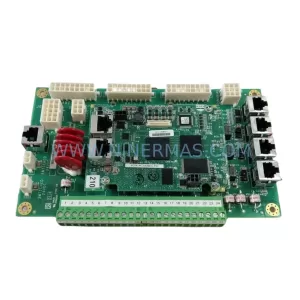
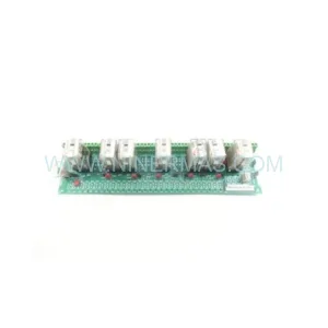
GE 350-E-P5-G5-H-E-E-N-W-SN-D-N | Feeder Retrofit & Modernization Relay
Catalog Continuation
Alternative parts within PLC & Industrial Automation Modules.
Stay inside the same system family when you need substitutes, adjacent modules, or a broader shortlist for procurement review.
SKU: KETOP T50 R01 VX/69908/14
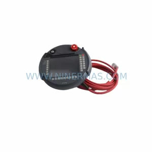
KEBA KETOP T50 R01 VX/69908/14 Service-Ready Spare Part
SKU: HMS01.1N-W0020-A-07-NNNN
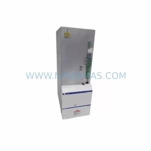
Rexroth HMS01.1N-W0020-A-07-NNNN Retrofit Single-Axis Servo Drive
SKU: SRZ-041 HB-R54VD-01 0050-90653 0100-09131
Heidenhain SRZ 041 HB R54VD 01 Retrofit Encoder Legacy Systems