Original Industrial Spare Part
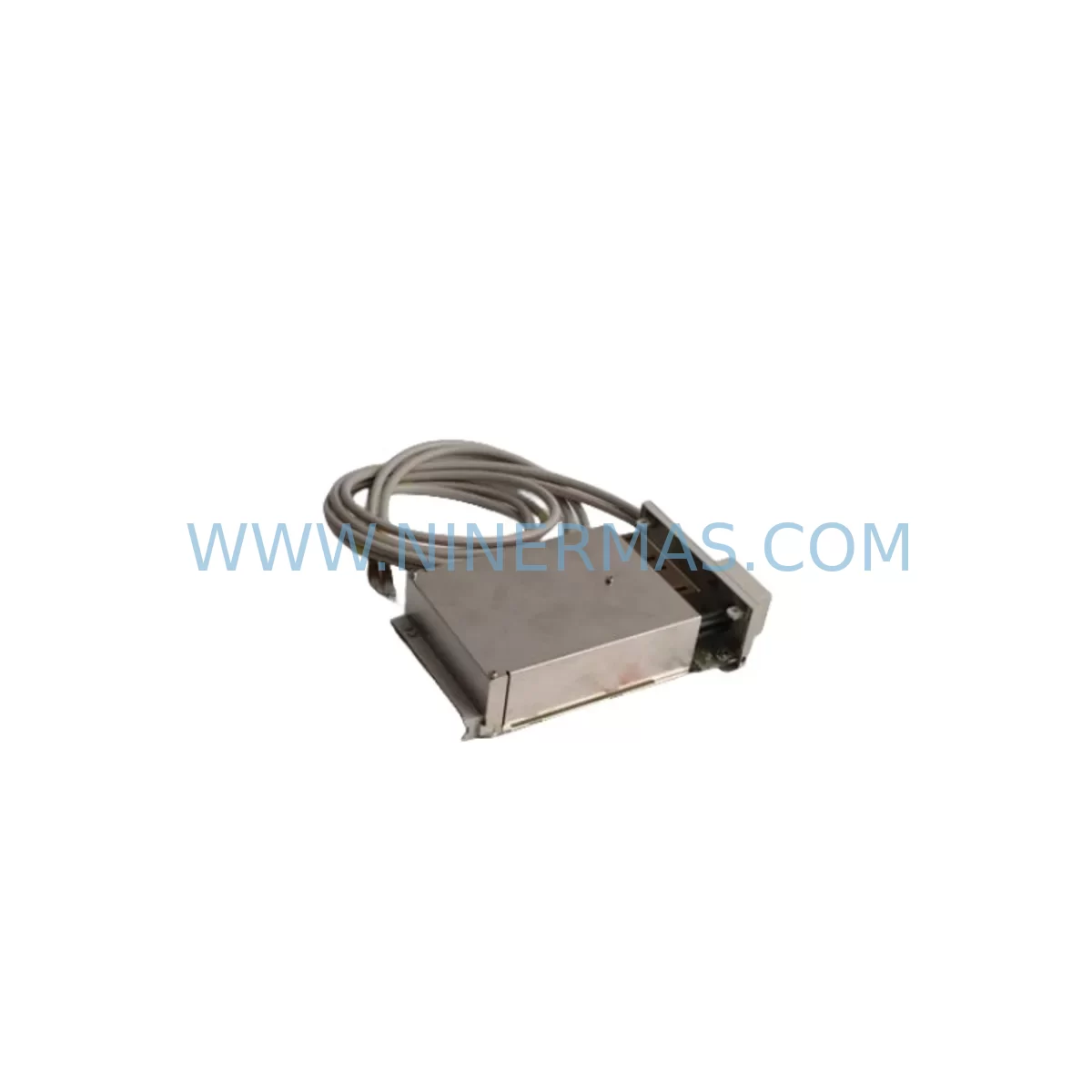
B&R 4PP220.0571-45 Retrofit-Compatible Panel for Legacy Systems
Verify the part, confirm the platform family, and move straight into quotation with the right commercial details.
RFQ Ready
- SKU4PP220.0571-45
- CategoryPLC & Industrial Automation Modules
- BrandB&R
- SupportAvailability, lead time, condition, and shipping coordination
How Buyers Usually Use This Page
- Confirm the exact part number and platform family before sending the quote request.
- Use direct email when quantity, condition, and destination are already defined internally.
- Switch to the broader brand or category archive when you need alternates nearby.
Series Navigation
Move through the most common platform families behind this part.
Product RFQ
Send this part directly for quotation.
Include quantity, required condition, destination country, and target delivery timing. Current reference: B&R 4PP220.0571-45 Retrofit-Compatible Panel for Legacy Systems with SKU 4PP220.0571-45.
B&R 4PP220.0571-45 Retrofit-Compatible Panel for Legacy Systems
The B&R 4PP220.0571-45 is a high-performance industrial panel PC designed for seamless integration into existing B&R automation environments. As legacy control systems approach end-of-life, this unit serves as a proven retrofit solution for facilities operating older B&R Power Panel and Automation PC platforms. Whether you are replacing a failed display module, upgrading a discontinued HMI terminal, or modernizing a control cabinet without rewriting the entire application, the 4PP220.0571-45 provides a reliable, drop-in-compatible upgrade path that minimizes engineering risk and reduces unplanned downtime.
This panel is particularly well-suited for production lines that were originally commissioned with B&R 4PP220 series hardware and have since encountered obsolescence challenges. The unit supports the B&R Automation Runtime environment, allowing existing PLC programs, visualization screens, and communication configurations to be migrated or reused with minimal modification. Engineers familiar with B&R Automation Studio will find the commissioning process straightforward, especially when paired with existing project archives.
Upgrade Compatibility Table
| Parameter | Details |
|---|---|
| SKU / Part Number | 4PP220.0571-45 |
| Brand / Manufacturer | B&R Industrial Automation |
| Series | 4PP220 Power Panel |
| Display Size | 5.7-inch TFT LCD |
| Interface Compatibility | B&R backplane bus, USB, CF card slot, serial COM ports |
| Communication Protocols | POWERLINK, CANopen, Modbus RTU/TCP (via add-on modules) |
| Mounting | Panel cutout mount; compatible with standard 4PP220 cabinet cutout dimensions |
| Power Supply | 24 VDC nominal; verify existing PSU capacity before installation |
| Replacement Compatibility | Direct replacement for 4PP220.0571-45; compatible migration from 4PP220.0571-35 and similar variants |
| Commissioning Notes | Restore project via Automation Studio; verify IP address, node ID, and I/O mapping |
| Pre-Shipment Testing | Yes — powered on and functionally verified before dispatch |
| Warranty | 12 Months from date of shipment |
| Origin | Austria (B&R headquarters; Eggelsberg) |
Retrofit Planning for Existing Automation Systems
Successful retrofit of the 4PP220.0571-45 into a legacy control cabinet requires a structured pre-installation review. Begin by auditing the existing 24 VDC power supply — typically a B&R 0PS1200.1 or equivalent DIN-rail PSU — to confirm it can sustain the panel’s peak current draw alongside other loads such as digital I/O modules and communication interfaces. Insufficient power headroom is one of the most common causes of intermittent faults after panel replacement.
Next, document the existing terminal wiring layout. The 4PP220.0571-45 uses a standard B&R connector scheme, but field wiring for analog inputs, digital outputs, and serial communication lines must be verified against the original cabinet drawings. If the legacy system included a B&R X20 I/O expansion rack — for example, X20CP1485 or X20DI9371 modules — confirm that the backplane addressing and slot assignments remain consistent with the restored Automation Studio project.
For facilities running POWERLINK-based motion control networks, verify that the 4PP220.0571-45 is assigned the correct Managing Node or Controlled Node role within the network topology. If the system also includes B&R ACOPOS servo drives or ACOPOSmulti drive modules, the POWERLINK cycle time and node configuration must be preserved exactly as defined in the original project to avoid axis faults on startup.
Where the legacy system relied on CANopen for field device communication — such as connecting to remote I/O stations, encoders, or valve terminals — the CANopen baud rate, node IDs, and PDO mapping must be re-verified after the panel swap. A B&R IF661 CANopen interface module or equivalent should be confirmed present and correctly seated in the panel’s interface slot.
HMI visualization screens built in B&R Automation Studio’s mapp View or VC4 environment can typically be restored directly from the project archive. However, if the original panel ran an older VC3 or VC2 visualization, a migration step to VC4 may be required. This is an appropriate time to review alarm pages, trend displays, and recipe management screens for any hardcoded IP addresses or device references that may need updating.
If the control cabinet also houses a B&R X20BC0083 POWERLINK bus controller or a legacy 2005 system bus coupler, confirm that firmware versions are compatible with the Automation Runtime version loaded on the 4PP220.0571-45. Mismatched firmware between the panel and bus controllers is a known source of communication errors during first-time startup after a panel replacement.
Finally, verify physical installation clearances. The 4PP220.0571-45 requires adequate rear-panel depth for cable routing and ventilation. In compact cabinets originally designed for an older 4PP220 variant, confirm that the replacement unit’s depth and connector positions do not conflict with existing cable trays or adjacent components such as a B&R 4AC power supply module or terminal block rows.
Downtime Control During System Migration
Minimizing production downtime during a panel replacement is a primary concern for maintenance teams. The recommended approach is to prepare a complete offline backup of the existing Automation Studio project — including all PLC programs, visualization pages, motion parameters, and communication configurations — before any hardware is removed from the cabinet. This backup should be stored on a local engineering workstation as well as a secure network location.
Where possible, perform the physical panel swap during a scheduled maintenance window rather than in response to an emergency failure. A pre-planned replacement allows time to bench-test the 4PP220.0571-45 with the restored project before it is installed in the live cabinet, significantly reducing the risk of startup delays on the production floor.
During the swap, label all field wiring before disconnection and photograph the original terminal layout. Restore the Automation Studio project to the new panel via USB or Ethernet download, then verify communication links to all connected devices — including POWERLINK nodes, CANopen slaves, and any Modbus TCP peripherals — before releasing the system to production. A structured commissioning checklist covering power-on sequence, I/O verification, motion axis homing, and HMI screen navigation will help the maintenance team confirm full system functionality within a defined time window.
For critical processes where even brief interruptions are unacceptable, consider staging the new panel in a parallel test configuration using a duplicate I/O rack or simulation environment before the live cutover. This approach allows program logic and visualization screens to be validated without interrupting the running process.
Retrofit Support FAQ
Q1: Is the 4PP220.0571-45 a direct replacement for my existing 4PP220 panel?
In most cases, yes. The 4PP220.0571-45 is dimensionally and electrically compatible with other 4PP220 series variants sharing the same 5.7-inch display format and standard backplane interface. Minor differences in firmware version or installed interface modules may require a brief configuration step in Automation Studio. We recommend confirming your existing panel’s exact part number and Automation Runtime version before ordering.
Q2: What commissioning steps are required after installation?
After physical installation, restore the Automation Studio project to the panel via USB or Ethernet. Verify the panel’s IP address, POWERLINK node ID (if applicable), and I/O module addressing. Confirm all communication links are active, check analog and digital I/O signal levels against known reference values, and perform a full HMI screen navigation test before returning the system to automatic operation.
Q3: Has this unit been tested before shipment?
Yes. Every 4PP220.0571-45 unit dispatched by NINERMAS undergoes a pre-shipment power-on and functional verification test. Units are inspected for display integrity, interface port functionality, and boot sequence completion. A test record is retained internally. The unit ships with a 12-month warranty covering manufacturing defects and functional failures under normal operating conditions.
Q4: What is the lead time and stock availability?
We maintain stock of the 4PP220.0571-45 to support urgent replacement requirements. Standard dispatch is within 1–3 business days of order confirmation. For large-quantity orders or long-term supply agreements, please contact our sales team directly to discuss availability and scheduling. All units are covered by a 12-month warranty from the date of shipment.
| Product Series | Legacy |
|---|---|
| Country of Origin | AT |
Catalog Continuation
More B&R modules in the catalog.
Use the brand lane to compare nearby part numbers, platform-adjacent modules, and other inquiry-ready listings before sending your final RFQ.
SKU: 5PP520.1043-00
B&R 5PP520.1043-00 Retrofit Power Panel for Legacy Systems
SKU: 4PP045.0571-062
B&R 4PP045.0571-062 Retrofit-Compatible Panel for Legacy Systems
Catalog Continuation
Alternative parts within PLC & Industrial Automation Modules.
Stay inside the same system family when you need substitutes, adjacent modules, or a broader shortlist for procurement review.
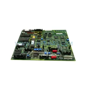
SKU: 531X133PRUALG1
GE 531X133PRUALG1 Retrofit-Compatible Process Interface Board
SKU: IRB7600 3HAC17484-1 3HAC062339-006 IRB6620 3HAC025007-001 DSQC1018 3HAC050363-001 DSQC1000 3HAC042766-001
ABB 3HAC17484-1 Service-Ready Spare for Industrial Maintenance
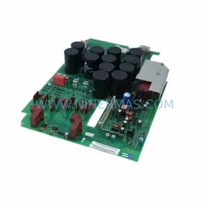
SKU: 6SE7023-4TC84-1HF3
Siemens 6SE7023-4TC84-1HF3 Service-Ready Industrial Spare