Original Industrial Spare Part
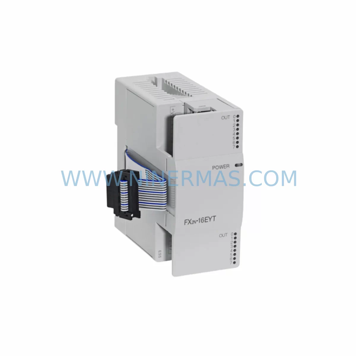
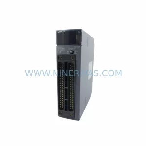
MITSUBISHI FX0N-16EYT Retrofit-Compatible Transistor Output for Legacy Systems
Verify the part, confirm the platform family, and move straight into quotation with the right commercial details.
RFQ Ready
- SKUFXON-16EYT
- CategorySIS Safety & Redundancy Systems
- BrandMitsubishi
- SupportAvailability, lead time, condition, and shipping coordination
How Buyers Usually Use This Page
- Confirm the exact part number and platform family before sending the quote request.
- Use direct email when quantity, condition, and destination are already defined internally.
- Switch to the broader brand or category archive when you need alternates nearby.
Series Navigation
Move through the most common platform families behind this part.
Product RFQ
Send this part directly for quotation.
Include quantity, required condition, destination country, and target delivery timing. Current reference: MITSUBISHI FX0N-16EYT Retrofit-Compatible Transistor Output for Legacy Systems with SKU FXON-16EYT.
MITSUBISHI FX0N-16EYT Retrofit-Compatible Transistor Output for Legacy Systems
The MITSUBISHI FX0N-16EYT is a 16-point transistor (sink) output expansion module designed for the FX0N series programmable logic controller platform. As production lines built around the FX0N family approach end-of-life support cycles, the FX0N-16EYT has become one of the most sought-after retrofit components for engineers tasked with keeping legacy automation systems operational without a full platform migration. Whether you are replacing a failed output module on an existing FX0N base unit, expanding I/O capacity on a control cabinet that was originally commissioned in the 1990s or early 2000s, or bridging the gap while a full system upgrade is planned, the FX0N-16EYT provides a direct, low-risk path to restoring and extending system functionality.
This module connects to the FX0N CPU unit via the dedicated extension bus connector on the right side of the base unit. It supports up to 16 transistor sink outputs rated at 24 VDC, with a maximum load current of 0.5 A per point and 0.8 A per common. The transistor output type makes it well suited for driving servo amplifier pulse inputs, stepper motor drivers, high-speed solenoid valves, and other inductive or capacitive loads where relay contact bounce or arc erosion would otherwise shorten service life. Engineers replacing an older FX0N-16ER relay output module with the FX0N-16EYT should verify load voltage compatibility, as the transistor version requires an external 24 VDC supply rather than the dry contact switching offered by the relay variant.
Before installing the FX0N-16EYT into an existing control cabinet, technicians should confirm available backplane expansion slots on the FX0N CPU — the FX0N base unit supports a maximum of 128 I/O points across all connected extension modules, including the FX0N-8EX input expansion, FX0N-8EYT transistor output expansion, and FX0N-16EX 16-point input module. Module address assignment is automatic based on physical slot position, so inserting the FX0N-16EYT in a different slot than the original module will shift output addresses Y0 through Y17 (octal) and may require corresponding changes in the ladder logic program stored in the FX0N CPU. Always back up the existing program using a programming cable such as the SC-09 or USB-SC09-FX before disconnecting any module.
Upgrade Compatibility Table
| Parameter | FX0N-16EYT (This Module) | FX0N-16ER (Relay Variant) | Retrofit Notes |
|---|---|---|---|
| Output Type | Transistor Sink (NPN) | Relay Contact | Verify load is 24 VDC; relay loads may need interface relay |
| Output Points | 16 | 16 | Direct point-for-point replacement |
| Max Load Current | 0.5 A/point, 0.8 A/common | 2 A/point | Derate loads accordingly for transistor version |
| Supply Voltage | 24 VDC external | Dry contact (no supply needed) | Ensure 24 VDC rail is available in cabinet |
| Backplane Interface | FX0N extension bus connector | FX0N extension bus connector | Mechanically compatible; no adapter required |
| Communication Protocol | FX0N proprietary bus | FX0N proprietary bus | No protocol migration required |
| Installation Space | DIN rail, same footprint as FX0N-16ER | DIN rail | No cabinet modification required |
| Commissioning | Address auto-assigned by slot | Address auto-assigned by slot | Verify Y-address mapping after installation |
| Warranty | 12-Month Warranty included with every unit shipped by NINERMAS | ||
Retrofit Planning for Existing Automation Systems
Successful integration of the FX0N-16EYT into a legacy production line begins well before the module arrives on site. The first step is a thorough audit of the existing control cabinet to document the current I/O allocation, terminal wiring, and power distribution. In most FX0N-based systems, the CPU unit — typically an FX0N-24MR or FX0N-40MR — is mounted on a DIN rail alongside a 24 VDC power supply module, input terminal blocks, and one or more expansion modules. The FX0N-16EYT slots directly onto the right side of the last installed expansion module using the built-in bus connector, requiring no additional backplane or rack hardware.
Terminal wiring for the FX0N-16EYT uses a removable screw terminal block with 0.3 mm² to 0.75 mm² wire gauge. Engineers replacing an FX0N-16ER should note that the terminal layout is identical in pin count but the common terminal (COM) function differs: on the transistor module, COM is the 0 V reference for the external 24 VDC supply, whereas on the relay module COM is a floating contact common. Rewiring is straightforward but must be completed with the cabinet de-energized. Label all wires before removal and photograph the original terminal block to avoid transposition errors during reinstallation.
For systems that also include an FX0N-8EX input expansion module or an FX0N-16EX providing additional digital inputs, the I/O address map must be recalculated after any module insertion or removal. The FX0N CPU assigns addresses sequentially from left to right: the CPU’s built-in I/O is addressed first, followed by each extension module in physical order. If the FX0N-16EYT is inserted between two existing modules — for example, between an FX0N-8EX and an existing FX0N-8EYT — all downstream output addresses will shift by 16 points (octal Y20 becomes Y40, etc.), requiring a corresponding edit to the ladder program using GX Developer or GX Works2 software.
Communication link integrity should also be verified during the retrofit. FX0N systems that use an FX0N-232ADP RS-232C communication adapter or an FX0N-485ADP RS-485 adapter for SCADA connectivity or HMI communication — such as a GOT1000 series HMI panel — will not be affected by adding an output expansion module, as the communication adapters connect to the CPU’s left-side option port independently of the I/O bus. However, if the HMI screen uses device addresses that reference specific output coils (Y addresses), those screen elements must be updated to reflect any address changes caused by module repositioning. This is a common source of post-retrofit alarms and should be included in the commissioning checklist.
For applications involving signal isolation — particularly where the FX0N-16EYT drives loads in a different voltage domain or where ground loops are a concern — a signal isolator or interface relay module inserted between the transistor output and the field device is recommended. This is especially relevant in retrofit scenarios where the original relay output module was providing galvanic isolation that the transistor version does not inherently offer.
Downtime Control During System Migration
Minimizing unplanned downtime is the primary concern in any legacy system retrofit. For FX0N-16EYT installations, the recommended approach is to complete all pre-work — program backup, terminal documentation, address mapping verification, and spare parts staging — during a scheduled maintenance window rather than during an emergency breakdown response. A well-prepared technician can physically swap an FX0N output module and restore production in under 30 minutes if the replacement unit is on hand and the program backup is current.
Before powering down the cabinet, use the SC-09 programming cable or USB-SC09-FX adapter to read out the full ladder program from the FX0N CPU and save it to a PC running GX Developer. Verify the saved file by comparing the program checksum or step count against the previous backup. This step protects against the risk of program loss if the CPU battery has degraded — a common issue in systems that have been in service for more than five years. If the CPU is an FX0N-24MR or FX0N-40MR with a low battery warning active, replace the lithium battery (CR2032 or equivalent, depending on CPU revision) at the same time as the output module to avoid a second maintenance event.
After installing the FX0N-16EYT and reconnecting terminal wiring, power up the cabinet with the CPU in STOP mode. Use the programming software to force individual output coils (Y addresses) and verify that the corresponding field devices — solenoid valves, motor contactors, indicator lamps, or servo enable signals — respond correctly. This forced I/O test confirms both the wiring integrity and the address mapping before the system is returned to automatic operation. Document the test results and retain them as part of the cabinet maintenance record. Once all outputs are verified, switch the CPU to RUN mode and monitor the first production cycle closely for any unexpected behavior.
For systems where even a brief shutdown is not acceptable, a parallel commissioning approach can be used: install the FX0N-16EYT alongside the existing module (if a free expansion slot is available), map the new module’s outputs in the program, and perform a hot-cutover by transferring field wiring one circuit at a time during a low-production period. This approach requires careful program management but can reduce effective downtime to near zero.
Retrofit Support FAQ
Q: Is the FX0N-16EYT a direct drop-in replacement for the FX0N-16ER?
A: Mechanically and electrically at the backplane level, yes — both modules use the same FX0N extension bus connector and occupy the same DIN rail footprint. However, the output circuit type is different: the FX0N-16EYT uses NPN transistor sink outputs requiring an external 24 VDC supply, while the FX0N-16ER uses dry relay contacts. Field wiring to the terminal block must be reviewed and may need to be modified. Load devices that require dry contact switching (e.g., 110 VAC loads) will need an interposing relay when using the transistor module.
Q: Will I need to modify my ladder program after installing the FX0N-16EYT?
A: Only if the module is installed in a different physical slot than the original. The FX0N CPU assigns Y output addresses based on slot position from left to right. If the replacement module occupies the same slot, no program changes are required. If the slot position changes, output addresses will shift and the program must be updated accordingly using GX Developer or GX Works2 before returning the system to RUN mode.
Q: Does NINERMAS test units before shipment, and what warranty is provided?
A: Every FX0N-16EYT unit supplied by NINERMAS undergoes functional testing prior to dispatch, including output point verification and bus communication checks. All units are covered by a 12-month warranty from the date of shipment. In the event of a warranty claim, NINERMAS provides a replacement unit and technical support to minimize system downtime. Stock is maintained to support urgent retrofit and breakdown requirements.
Q: Can the FX0N-16EYT be used with FX1N or FX2N series CPUs?
A: The FX0N-16EYT is designed specifically for the FX0N series extension bus and is not compatible with FX1N, FX2N, or FX3U series CPUs, which use a different extension bus architecture. For FX1N or FX2N systems, the appropriate output expansion modules are the FX2N-16EYT or FX1N-40MR built-in I/O extensions. If you are planning a platform migration from FX0N to FX3U, NINERMAS can advise on the correct I/O expansion modules and communication adapters for the target platform.
| Product Series | FX0N |
|---|---|
| Country of Origin | JP |
Catalog Continuation
More Mitsubishi modules in the catalog.
Use the brand lane to compare nearby part numbers, platform-adjacent modules, and other inquiry-ready listings before sending your final RFQ.
Catalog Continuation
Alternative parts within SIS Safety & Redundancy Systems.
Stay inside the same system family when you need substitutes, adjacent modules, or a broader shortlist for procurement review.