Original Industrial Spare Part
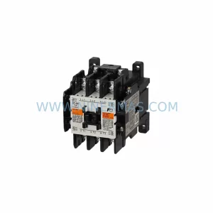
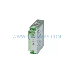
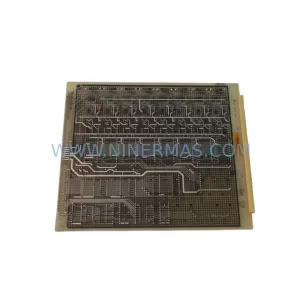
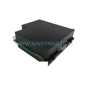
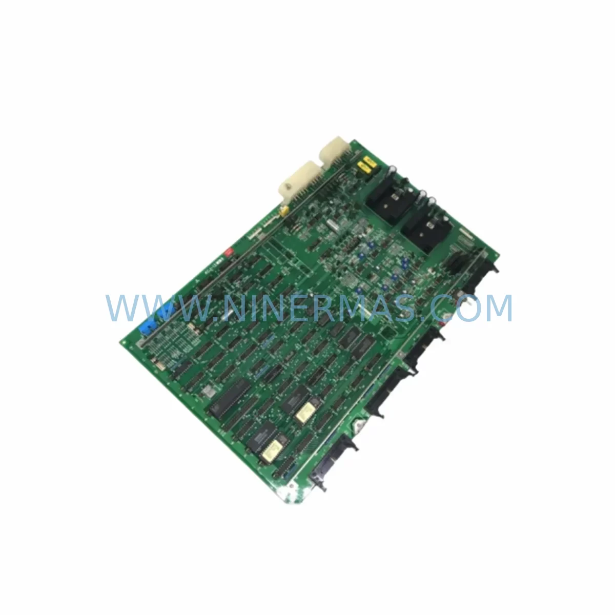
Mitsubishi KCJ-120B Retrofit-Compatible Relay for Legacy Systems
Verify the part, confirm the platform family, and move straight into quotation with the right commercial details.
RFQ Ready
- SKUKCJ-120B
- CategoryPLC & Industrial Automation Modules
- BrandMitsubishi
- SupportAvailability, lead time, condition, and shipping coordination
How Buyers Usually Use This Page
- Confirm the exact part number and platform family before sending the quote request.
- Use direct email when quantity, condition, and destination are already defined internally.
- Switch to the broader brand or category archive when you need alternates nearby.
Series Navigation
Move through the most common platform families behind this part.
Product RFQ
Send this part directly for quotation.
Include quantity, required condition, destination country, and target delivery timing. Current reference: Mitsubishi KCJ-120B Retrofit-Compatible Relay for Legacy Systems with SKU KCJ-120B.
Mitsubishi KCJ-120B Retrofit-Compatible Relay for Legacy Systems: Seamless Upgrade for Aging Automation Infrastructure
The Mitsubishi KCJ-120B is a relay module originally designed for use within Mitsubishi’s legacy PCB-based control platforms. As production lines age and original equipment manufacturers discontinue support for older automation architectures, the KCJ-120B has become a critical component in retrofit and modernization projects across manufacturing, utilities, and process control industries. Whether you are replacing a failed unit on an existing panel or executing a planned migration away from end-of-life control hardware, the KCJ-120B provides a reliable, verified path forward without requiring a full system overhaul.
At NINERMAS, we specialize in sourcing, testing, and supplying discontinued and hard-to-find industrial control components. Every KCJ-120B unit we ship undergoes functional verification prior to dispatch, and is backed by a 12-month warranty covering manufacturing defects and operational failure under normal use conditions. Our inventory is maintained to support urgent replacement needs, with same-day or next-business-day dispatch available for in-stock units.
Upgrade Compatibility Table
| Parameter | KCJ-120B Specification | Retrofit Notes |
|---|---|---|
| Module Type | Relay Output Module | Verify output type matches existing wiring (relay vs. transistor) |
| Mounting Interface | Legacy PCB backplane slot | Confirm backplane slot pitch and connector type before installation |
| Communication Protocol | Parallel backplane bus | Not compatible with CC-Link or MELSECNET without protocol bridge |
| Power Supply Requirement | 24VDC (typical) | Verify rack power supply capacity; consider upgrading to Q61P or Q62P if marginal |
| I/O Point Count | Per original PCB spec | Map I/O addresses before swapping; update GX Works2 or GX Developer program if required |
| Installation Space | Standard PCB card form factor | Measure card guide clearance; confirm no physical interference with adjacent modules |
| Replacement Recommendation | Direct drop-in for same-series PCB racks | Cross-reference with A1S series or Q series migration path if full upgrade is planned |
| Commissioning Focus | Terminal wiring, address assignment, output verification | Use GX Developer or GX Works2 for online monitoring during first power-up |
| Warranty | 12 Months — covers manufacturing defects and operational failure under normal use | |
Retrofit Planning for Existing Automation Systems
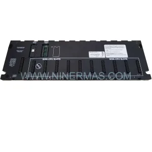
Successful integration of the KCJ-120B into an existing control system requires careful pre-installation planning. Engineers undertaking a retrofit should begin by auditing the existing rack configuration. In many legacy Mitsubishi A-series or early Q-series installations, the control rack may house a combination of components including the A1SCPU or A2SCPU controller, A1S62P or A1S63P power supply modules, and a mix of input and output cards occupying fixed slot addresses. The KCJ-120B occupies a defined slot position, and any change to slot assignment must be reflected in the PLC program’s I/O map.
Before removing the existing relay card, engineers should export the current PLC program using GX Developer or GX Works2 and document all I/O comments, device assignments, and network parameters. If the system includes an A1SJ71UC24-R4 serial communication module or an A1SJ71E71-B5 Ethernet module, communication link parameters must be preserved and re-verified after the card swap. Disrupting the communication module configuration is one of the most common causes of extended downtime during relay module replacement.
Terminal wiring is another critical checkpoint. The KCJ-120B uses a screw-terminal or connector-based interface depending on the PCB revision. Before disconnecting field wiring, photograph or document each terminal connection. Use a wiring label system to tag each conductor. If the existing terminal block is worn or corroded, this is an appropriate time to replace it with a compatible Mitsubishi terminal block assembly or equivalent DIN-rail mounted terminal strip.
Power supply capacity must also be confirmed. Legacy racks running multiple output modules may be operating near the rated output current of the installed A1S62P power supply. Adding or replacing a relay module without checking the total current draw can result in nuisance tripping or power supply failure. If the power budget is tight, consider upgrading to a higher-capacity supply such as the Q62P as part of the same maintenance window.
For systems that include an A1SD71 positioning module or an A1SJ71AP23Q MELSECNET/MINI-S3 master module, ensure that the relay output signals interfacing with these modules are correctly re-mapped after the KCJ-120B installation. Positioning and network modules are sensitive to I/O timing, and any address offset introduced during the retrofit must be corrected in both the PLC program and the HMI screen tag database.
If the facility uses a GOT1000 or GOT2000 series HMI panel connected to the legacy controller, HMI screen tags referencing relay output devices must be reviewed. Tag addresses that pointed to the original relay card’s output coils should be verified against the new I/O map. Failure to update HMI tags is a frequent source of post-retrofit alarms and operator confusion.
Finally, if the retrofit is part of a broader migration toward a Q-series or iQ-R series platform, the KCJ-120B installation can serve as an interim measure while the full migration is planned. In this scenario, the relay module stabilizes the existing system, extends its operational life, and buys the engineering team time to develop and test the new control program without production pressure.
Downtime Control During System Migration
Minimizing downtime during a relay module replacement requires a structured approach. Begin by scheduling the swap during a planned maintenance window, ideally during a shift change or weekend shutdown. Prepare all replacement components, tools, and documentation in advance so that the physical swap can be completed within the allocated window.
Before powering down the rack, place the PLC in STOP mode and verify that all field outputs are in a safe state. For systems controlling conveyors, actuators, or process valves, coordinate with operations to confirm that the line is in a safe condition before de-energizing the control panel. Use the GX Developer or GX Works2 online monitor to confirm output status before and after the STOP command.
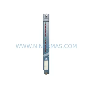
Once the KCJ-120B is installed, power up the rack and observe the module status LEDs. A healthy module should illuminate its RUN or READY indicator within a few seconds of power application. If a fault LED is active, check the slot address assignment in the PLC program and verify that the module type matches the program’s I/O declaration. Use the GX Works2 system monitor to read module diagnostic information without requiring a full program download.
After confirming module status, switch the PLC to RUN mode and perform a controlled output test. Activate each relay output individually using the GX Developer force output function and verify field device response at the terminal. This step confirms wiring integrity and relay contact operation before returning the line to production.
Document the completed retrofit in the system maintenance log, including the date, replaced component serial number, technician name, and any deviations from the original wiring or program. This record supports future troubleshooting and demonstrates compliance with maintenance procedures for audits or insurance purposes.
Retrofit Support FAQ
Q1: Is the KCJ-120B a direct drop-in replacement for the original Mitsubishi PCB relay card in my A-series rack?
In most cases, yes. The KCJ-120B is designed to fit the same backplane slot and terminal interface as the original card in compatible A-series PCB racks. However, you should verify the slot connector type, terminal pitch, and I/O address assignment before installation. If your rack uses a non-standard backplane revision, contact us with your rack model number for confirmation.
Q2: Do I need to modify my PLC program after installing the KCJ-120B?
If the replacement module occupies the same slot address as the original and the I/O point count is identical, no program modification is required. However, if the slot address has changed or the module type declaration in GX Developer or GX Works2 does not match, you will need to update the I/O map and re-download the program. Always perform an online comparison between the existing program and the updated version before switching to RUN mode.
Q3: What testing is performed on KCJ-120B units before shipment?
Every KCJ-120B unit supplied by NINERMAS undergoes functional verification including relay coil energization, contact continuity testing, and insulation resistance checks. Units that fail any test criterion are quarantined and not shipped. A test report is available upon request. All units are shipped with a 12-month warranty covering manufacturing defects and operational failure under normal use conditions.
Q4: What is your lead time and do you maintain stock of the KCJ-120B?
We maintain inventory of the KCJ-120B to support urgent replacement requirements. In-stock units are typically dispatched within one business day of order confirmation. For large quantity orders or long-term supply agreements, contact our sales team to discuss availability and scheduling. We can also source related components such as A-series backplane assemblies, power supply modules, and communication cards to support a complete retrofit bill of materials.
—
| Product Series | Legacy |
|---|---|
| Country of Origin | JP |
Catalog Continuation
More Mitsubishi modules in the catalog.
Use the brand lane to compare nearby part numbers, platform-adjacent modules, and other inquiry-ready listings before sending your final RFQ.
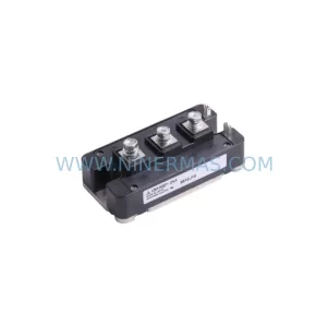
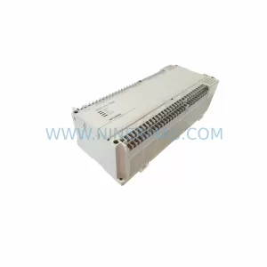
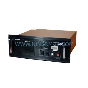
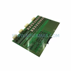
SKU: FT-600D(HVP P.S) FTI-600D-T6 USAHEM-02-TE53 2706-LV2R
Mitsubishi FT-600DHVP-P-S Retrofit Controller for Legacy Systems
Catalog Continuation
Alternative parts within PLC & Industrial Automation Modules.
Stay inside the same system family when you need substitutes, adjacent modules, or a broader shortlist for procurement review.