Original Industrial Spare Part
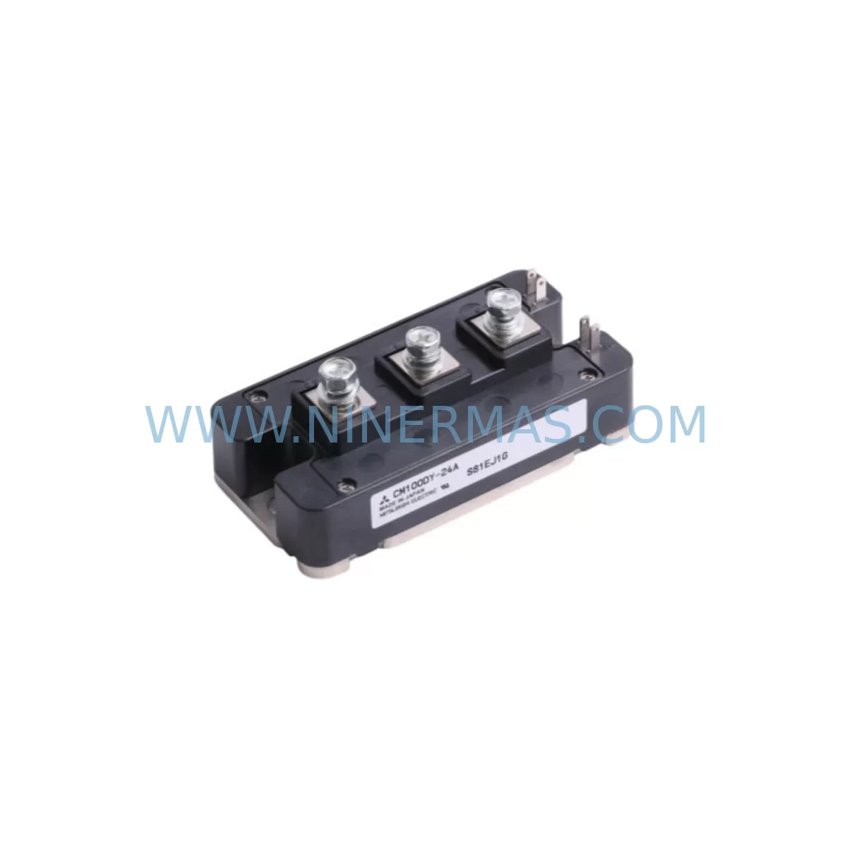
Mitsubishi CM100DY-24A Service-Ready Industrial Spare Part
Verify the part, confirm the platform family, and move straight into quotation with the right commercial details.
RFQ Ready
- SKUCM100DY-24A
- CategoryPLC & Industrial Automation Modules
- BrandMitsubishi
- SupportAvailability, lead time, condition, and shipping coordination
How Buyers Usually Use This Page
- Confirm the exact part number and platform family before sending the quote request.
- Use direct email when quantity, condition, and destination are already defined internally.
- Switch to the broader brand or category archive when you need alternates nearby.
Series Navigation
Move through the most common platform families behind this part.
Product RFQ
Send this part directly for quotation.
Include quantity, required condition, destination country, and target delivery timing. Current reference: Mitsubishi CM100DY-24A Service-Ready Industrial Spare Part with SKU CM100DY-24A.
Mitsubishi CM100DY-24A Service-Ready Industrial Spare Part: Spare Replacement & Downtime Risk Control
The Mitsubishi CM100DY-24A is a 100A / 1200V dual IGBT power module widely deployed in industrial inverter drives, servo amplifiers, UPS systems, and medium-voltage motor control centers. When this module fails in service, the consequences extend far beyond a single component — an unplanned shutdown of a production line, a conveyor system, or a process pump can cost thousands of dollars per hour. Sourcing a verified, original CM100DY-24A spare part in advance is the most effective strategy for minimizing mean time to repair (MTTR) and protecting operational continuity.
At NINERMAS, every CM100DY-24A unit is sourced from authorized distribution channels, individually inspected, and shipped with full traceability documentation. Our 12-month warranty covers manufacturing defects and ensures that your maintenance team receives a service-ready component — not a refurbished or counterfeit substitute. Whether you are replenishing a regional spare parts depot, responding to an emergency breakdown, or executing a planned annual overhaul, we provide reliable supply with fast lead times and pre-shipment electrical testing.
Spare Maintenance Table
| Parameter | Specification |
|---|---|
| SKU / Part Number | CM100DY-24A |
| Brand | Mitsubishi Electric |
| Series | CM Series (Dual IGBT Module) |
| Collector Current (IC) | 100 A |
| Collector-Emitter Voltage (VCES) | 1200 V |
| Gate-Emitter Voltage (VGES) | ±20 V |
| Package Type | Isolated Base Module (DY package) |
| Mounting | Screw-mount to heatsink; thermal grease required |
| Application Environment | Industrial inverter drives, servo amplifiers, UPS, motor control |
| Operating Temperature | –40°C to +150°C (junction) |
| Compatibility | Direct replacement for CM100DY-24A in Mitsubishi FR series drives and equivalent OEM platforms |
| Origin | Japan |
| Condition | Original, New |
| Pre-Shipment Testing | Electrical verification performed before dispatch |
| Warranty | 12 Months from date of shipment |
Maintenance Planning for Continuous Operation
Replacing the CM100DY-24A in the field is rarely an isolated task. Experienced maintenance engineers know that an IGBT module failure is often symptomatic of broader stress conditions within the power conversion cabinet. A thorough site inspection during the replacement window should encompass the entire power stage and control chain to prevent repeat failures and maximize the value of the planned downtime.
Begin with the gate driver board. The CM100DY-24A is typically driven by a dedicated gate driver circuit — in Mitsubishi FR-series drives, this is often a PS-26 or equivalent isolated gate driver card. A failed IGBT can inject reverse voltage spikes that damage the gate driver output stage; always verify gate resistor values and optocoupler integrity before powering up the replacement module. Inspect the DC bus capacitor bank for bulging, leakage, or elevated ESR — degraded bus capacitors are a leading cause of IGBT overvoltage stress and premature failure.
On the control side, check the power supply module feeding the control board. In MELSEC-Q series or A-series PLC cabinets integrated with the drive system, the A1S61PN or Q61P power supply module should be verified for stable 5 VDC and 24 VDC output under load. Unstable control power can cause erratic gate signals and false fault trips that stress the power module unnecessarily.
Review the I/O interface between the drive and the PLC. Faulty 24 VDC I/O signals — particularly run/stop commands and fault reset lines — can cause repeated hard switching events that accelerate IGBT wear. If the system uses a QJ71BR11 or CC-Link communication module for drive control, verify the communication cable shielding and termination resistors, as noise on the fieldbus can generate spurious speed reference changes that stress the power stage.
For systems using a CM150DY-24A or CM200DY-24A in parallel or in adjacent drive cabinets, cross-check those modules for early signs of degradation — elevated on-state voltage drop or asymmetric thermal profiles on the heatsink are indicators that a companion module may be approaching end of life. Stocking a CM50DY-24A for smaller auxiliary drives in the same facility is also advisable, as these share the same CM-series package and installation procedure.
Do not overlook the thermal management system. Clean the heatsink fins, verify fan operation, and apply fresh thermal interface material when reinstalling the CM100DY-24A. Thermal resistance degradation is one of the most common causes of IGBT derating and shortened service life in high-ambient industrial environments.
Finally, if the control cabinet includes a GOT2000 series HMI for drive monitoring, use the diagnostic screens to log fault history and verify that the new module is operating within normal current and temperature envelopes during the post-replacement commissioning run. Document the replacement in your CMMS and schedule a follow-up inspection at 500 operating hours.
Site Replacement Workflow
Step 1 — Isolation & Lockout/Tagout: De-energize the drive, discharge the DC bus capacitors to below 30 VDC (verify with a calibrated meter), and apply LOTO before opening the power cabinet.
Step 2 — Module Removal: Photograph the existing wiring and bus bar connections. Remove the collector and emitter bus bar bolts, then the gate/emitter signal leads. Unscrew the module mounting screws and carefully lift the CM100DY-24A from the heatsink. Note the torque values specified in the drive service manual.
Step 3 — Heatsink Preparation: Clean residual thermal compound from the heatsink surface using isopropyl alcohol. Inspect the heatsink for cracks or corrosion. Apply a thin, uniform layer of thermal interface material to the new module base.
Step 4 — Module Installation: Position the replacement CM100DY-24A, torque mounting screws to specification (typically 3–5 Nm), reconnect bus bars and signal leads in reverse order of removal. Verify gate resistor connections and confirm no signal leads are reversed.
Step 5 — Pre-Power Verification: With control power only, verify gate driver output signals are within specification. Check for any fault codes on the drive display or GOT2000 HMI before enabling the main power stage.
Step 6 — Commissioning Run: Restore main power, run the drive at low speed under no-load conditions, and monitor output current balance and heatsink temperature. Gradually increase to full load and confirm stable operation before returning the line to production.
This workflow is compatible with Mitsubishi FR-A700, FR-F700, FR-E700, and equivalent drive platforms that use the CM100DY-24A power module. The same procedure applies when upgrading from an end-of-life variant to a current-production replacement, ensuring system compatibility is maintained without firmware or parameter changes.
Spare Parts Support FAQ
Q1: Is the CM100DY-24A still in production, and can NINERMAS guarantee long-term supply?
The CM100DY-24A remains available through authorized distribution channels. NINERMAS maintains strategic stock and works with a global supplier network to ensure continued availability for legacy system support. We can provide supply commitments for multi-year maintenance contracts upon request.
Q2: How do I verify compatibility before installation?
Confirm the part number on the existing module label matches CM100DY-24A exactly. Cross-reference the drive service manual for the approved module list. If you are substituting from an adjacent CM-series variant, verify that the current rating, voltage class, and package dimensions are identical before installation. NINERMAS technical support can assist with compatibility verification prior to order placement.
Q3: What pre-shipment testing does NINERMAS perform on each unit?
Every CM100DY-24A dispatched by NINERMAS undergoes electrical verification including VCES blocking voltage check, gate threshold voltage measurement, and on-state resistance spot-check. Units that do not meet Mitsubishi Electric published datasheet parameters are quarantined and not shipped. A test report is available upon request.
Q4: What does the 12-month warranty cover, and how is a warranty claim processed?
The 12-month warranty covers manufacturing defects and electrical parameter non-conformance under normal operating conditions. It does not cover damage resulting from incorrect installation, overvoltage events, or operation outside rated parameters. To initiate a warranty claim, contact NINERMAS with the original invoice, a description of the failure mode, and photographs of the installed module. Replacement or credit will be processed within 10 business days of claim approval.
| Product Series | Other series |
|---|---|
| Country of Origin | JP |
Catalog Continuation
More Mitsubishi modules in the catalog.
Use the brand lane to compare nearby part numbers, platform-adjacent modules, and other inquiry-ready listings before sending your final RFQ.
SKU: FT-600D(HVP P.S) FTI-600D-T6 USAHEM-02-TE53 2706-LV2R
Mitsubishi FT-600DHVP-P-S Retrofit Controller for Legacy Systems
Catalog Continuation
Alternative parts within PLC & Industrial Automation Modules.
Stay inside the same system family when you need substitutes, adjacent modules, or a broader shortlist for procurement review.