Original Industrial Spare Part
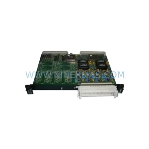
GE 20X4584-10A Retrofit-Compatible Output Board
Verify the part, confirm the platform family, and move straight into quotation with the right commercial details.
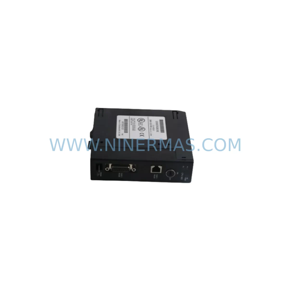
RFQ Ready
- SKU20X4584-10A
- CategoryPLC & Industrial Automation Modules
- BrandGE
- SupportAvailability, lead time, condition, and shipping coordination
How Buyers Usually Use This Page
- Confirm the exact part number and platform family before sending the quote request.
- Use direct email when quantity, condition, and destination are already defined internally.
- Switch to the broader brand or category archive when you need alternates nearby.
Series Navigation
Move through the most common platform families behind this part.
Product RFQ
Send this part directly for quotation.
Include quantity, required condition, destination country, and target delivery timing. Current reference: GE 20X4584-10A Retrofit-Compatible Output Board with SKU 20X4584-10A.
GE 20X4584-10A Retrofit-Compatible Output Board for Legacy Automation Systems
The GE 20X4584-10A is a retrofit-compatible output board designed for integration into legacy GE Series 90-70 programmable logic controller (PLC) platforms. As industrial facilities face increasing pressure to extend the operational life of aging control infrastructure, the 20X4584-10A provides a reliable, field-proven solution for engineers managing discontinued spare part replacement, control cabinet upgrades, and phased system modernization programs. Whether you are maintaining a continuous process line, a discrete manufacturing cell, or a hybrid automation environment, this output board supports smooth migration without requiring a full controller replacement.
At NINERMAS, every 20X4584-10A unit undergoes pre-shipment functional testing to verify output channel integrity, backplane communication, and signal response under load conditions. Stock is maintained to support both emergency breakdown orders and planned lifecycle extension programs, with a standard 12-month warranty covering all tested units.
Upgrade Compatibility Table
| Parameter | Details |
|---|---|
| Part Number | GE 20X4584-10A |
| Compatible Platform | GE Series 90-70 PLC |
| Module Type | Output Board / Output Module |
| Backplane Interface | Series 90-70 VME-based backplane (IC697 rack compatible) |
| Installation Form Factor | Standard 90-70 rack slot; confirm slot width and rack depth before installation |
| Communication Compatibility | Compatible with GE Genius Bus, SNP/SNPX serial protocols used in legacy 90-70 configurations |
| Replacement Recommendation | Direct replacement for failed or end-of-life 20X4584-10A boards; verify output channel count and wiring terminal layout against existing field wiring |
| Commissioning Notes | Confirm module address configuration, I/O table mapping in Logicmaster 90 or Proficy Machine Edition, and HMI tag bindings before energizing outputs |
| Power Supply Requirement | Verify rack power supply capacity (e.g., IC697PWR711 or IC697PWR724) supports additional module load |
| Warranty | 12 months from shipment date, covering manufacturing defects and functional failure under normal operating conditions |
Retrofit Planning for Existing Automation Systems
Replacing the GE 20X4584-10A in an operating plant requires careful pre-work to avoid unplanned downtime and configuration errors. The first step is a physical audit of the existing rack assembly. In a typical Series 90-70 installation, the rack may house a combination of the IC697CPU772 or IC697CPU781 central processing unit, alongside power supply modules such as the IC697PWR711, analog input modules like the IC697ALG230, and discrete I/O modules including the IC697MDL340 or IC697MDL753. Each of these components occupies a defined slot position, and the 20X4584-10A output board must be installed in the correct slot to match the I/O configuration table stored in the CPU.
Before removing the existing board, engineers should export the current PLC program using Logicmaster 90-70 or Proficy Machine Edition programming software and save a verified backup. The I/O configuration, including the rack number, slot number, and module reference address, must be documented. If the facility uses a GE Genius Bus Controller (IC697BEM731) for distributed I/O communication, the bus address assignments and block transfer parameters should also be recorded to prevent communication faults after the swap.
Terminal wiring is a critical checkpoint. The field wiring connected to the 20X4584-10A output terminals must be labeled and photographed before disconnection. Output channel polarity, load current ratings, and common terminal groupings should be verified against the original wiring diagram. In installations where a terminal block adapter (IC697ACC724) or pre-wired cable assembly is used, confirm that the replacement board uses the same connector pinout to avoid rewiring the field side.
For facilities that have integrated the Series 90-70 system with an HMI panel — such as a GE QuickPanel or a third-party SCADA workstation communicating via SNP or Ethernet — the output tag addresses displayed on operator screens must be verified after the module swap. Any change in rack slot assignment will require an update to the HMI tag database and a screen-by-screen validation to confirm that output status indicators, interlock displays, and alarm setpoints reflect the correct I/O addresses.
Where the control system includes a GE IC697CMM742 communications module for Modbus RTU or ASCII serial communication to third-party devices, the communication link should be tested independently after the output board replacement to confirm that the CPU scan cycle and communication task scheduling have not been disrupted. Signal isolators installed between the PLC output channels and field devices — particularly in high-voltage or intrinsically safe zones — should also be inspected for compatibility with the replacement board’s output drive characteristics.
Downtime Control During System Migration
Minimizing production interruption during a 20X4584-10A replacement requires a structured change management approach. Where process conditions allow, the replacement should be scheduled during a planned maintenance window rather than as an emergency repair. A pre-staged replacement board, verified through bench testing against a known-good rack or test fixture, eliminates the risk of installing a second faulty unit under time pressure.
Before initiating the physical swap, the PLC program should be placed in STOP mode following the facility’s lockout/tagout (LOTO) procedure. The existing output board should be removed only after confirming that all controlled field devices — motors, valves, actuators, and interlocks — are in a safe, de-energized state. The replacement 20X4584-10A should be inserted into the same rack slot, with the module address switches (if applicable) set to match the original configuration.
After installation, the CPU should be powered up in STOP mode first to allow the I/O configuration to be verified before outputs are enabled. The engineer should confirm that the module status LED indicates normal operation and that no I/O fault codes are present in the CPU fault table. Only after a clean I/O scan with no faults should the PLC be transitioned to RUN mode and field outputs re-energized in a controlled sequence. HMI screens should be monitored during the first production cycle to confirm that all output status displays and interlock logic are functioning as expected.
For systems where a cold restart is not acceptable — such as continuous chemical processes or safety-instrumented systems — a hot-swap or redundant output strategy using a parallel rack with an IC697RCM711 redundancy control module may be appropriate. NINERMAS can advise on redundancy configurations and supply matched pairs of tested output boards for dual-rack installations.
Retrofit Support FAQ
Q1: Is the GE 20X4584-10A a direct drop-in replacement for the original board?
In most Series 90-70 installations, yes. The 20X4584-10A is designed to fit the standard VME-based backplane slot used in IC697 racks. However, you should verify the output channel count, terminal wiring layout, and module address configuration against your existing I/O table before installation. NINERMAS provides a datasheet and wiring reference with each shipment to support this verification.
Q2: Has the unit been tested before shipment?
Yes. Every 20X4584-10A supplied by NINERMAS undergoes pre-shipment functional testing, including output channel activation, backplane communication verification, and load response checks. A test report is available upon request. All units are covered by a 12-month warranty from the date of shipment.
Q3: What programming software is required to commission the replacement board?
The GE Series 90-70 platform is programmed using Logicmaster 90-70 (legacy) or Proficy Machine Edition (current). The I/O configuration must be updated in the hardware configuration tool to reflect the installed module type and slot position. If you are migrating from an older CPU revision, confirm that the firmware version supports the 20X4584-10A module reference.
Q4: Can NINERMAS supply multiple units for a long-term spare parts program?
Yes. NINERMAS maintains stock of the GE 20X4584-10A and can support both single-unit emergency orders and bulk procurement for lifecycle extension programs. Lead times and volume pricing are available on request. Contact our team at sale@ninermas.com or +0086 187 5021 5667 to discuss your spare parts requirements.
| Product Series | 90-70 |
|---|---|
| Country of Origin | US |
Catalog Continuation
More GE modules in the catalog.
Use the brand lane to compare nearby part numbers, platform-adjacent modules, and other inquiry-ready listings before sending your final RFQ.

Catalog Continuation
Alternative parts within PLC & Industrial Automation Modules.
Stay inside the same system family when you need substitutes, adjacent modules, or a broader shortlist for procurement review.
SKU: PFXPP170CA66K00N00
Pro-face PFXPP170CA66K00N00 Service-Ready Spare Part

SKU: 6SL3224-0BE32-2UA0
Siemens 6SL3224-0BE32-2UA0 Retrofit PM240 Power Module