Original Industrial Spare Part
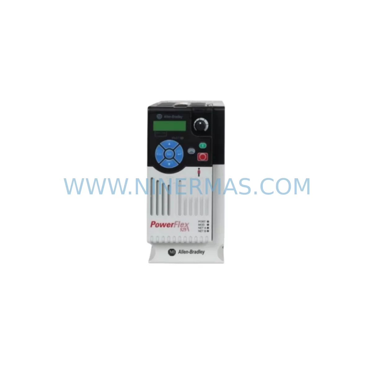
Allen-Bradley 25B-D010N104 Retrofit-Compatible AC Drive for Legacy Systems
Verify the part, confirm the platform family, and move straight into quotation with the right commercial details.
RFQ Ready
- SKU25B-D010N104
- CategoryPLC & Industrial Automation Modules
- BrandAllen-Bradley
- SupportAvailability, lead time, condition, and shipping coordination
How Buyers Usually Use This Page
- Confirm the exact part number and platform family before sending the quote request.
- Use direct email when quantity, condition, and destination are already defined internally.
- Switch to the broader brand or category archive when you need alternates nearby.
Series Navigation
Move through the most common platform families behind this part.
Product RFQ
Send this part directly for quotation.
Include quantity, required condition, destination country, and target delivery timing. Current reference: Allen-Bradley 25B-D010N104 Retrofit-Compatible AC Drive for Legacy Systems with SKU 25B-D010N104.
Allen-Bradley 25B-D010N104 Retrofit-Compatible AC Drive for Legacy Systems
The Allen-Bradley 25B-D010N104 is a PowerFlex 525 series AC drive rated at 10HP (7.5kW), 480V AC, three-phase input. Designed for embedded EtherNet/IP connectivity and modular architecture, this drive is a proven retrofit solution for aging automation lines previously controlled by PowerFlex 4, PowerFlex 40, or PowerFlex 400 series drives. For maintenance engineers and system integrators managing legacy control cabinets, the 25B-D010N104 delivers a direct upgrade path with minimal rewiring, reduced commissioning time, and full compatibility with existing Logix-based control platforms.
NINERMAS supplies the 25B-D010N104 from verified stock, pre-shipment tested, and backed by a 12-month warranty. Each unit is inspected for firmware integrity, terminal block condition, and drive parameter retention before dispatch. Whether you are replacing a failed drive on an active production line or building a spare parts inventory for lifecycle extension, this unit ships ready for installation.
Upgrade Compatibility Table
| Parameter | Details |
|---|---|
| Part Number | 25B-D010N104 |
| Series | PowerFlex 525 |
| Power Rating | 10HP / 7.5kW |
| Input Voltage | 480V AC, 3-Phase |
| Output Current | 10A (Normal Duty) |
| Communication | Embedded EtherNet/IP |
| Enclosure | IP20 / Open Type |
| Mounting | Panel / DIN Rail |
| Replaces | PowerFlex 4 (22A), PowerFlex 40 (22B), PowerFlex 400 (22C) |
| Control Platform Compatibility | Studio 5000 / RSLogix 5000 / CompactLogix / ControlLogix |
| Terminal Compatibility | Standard screw terminals; verify wire gauge against legacy wiring |
| Commissioning Tool | Connected Components Workbench (CCW) / DriveExecutive |
| Retrofit Recommendation | Direct replacement with parameter re-entry; verify accel/decel ramps and PID setpoints |
| Warranty | 12 Months — NINERMAS Quality Assurance |
Retrofit Planning for Existing Automation Systems
Replacing a legacy drive in an active production environment requires systematic planning across multiple subsystems. When migrating from a PowerFlex 40 (22B) or PowerFlex 400 (22C) to the 25B-D010N104, the first step is to document all existing parameter settings using DriveExecutive or a manual parameter sheet. Key parameters include acceleration time (P041), deceleration time (P042), minimum and maximum frequency limits, motor nameplate data, and any PID reference configurations tied to analog input cards.
The 25B-D010N104 uses a standard 24VDC digital input architecture compatible with most existing control wiring. However, engineers should verify the terminal block layout against the legacy drive’s I/O wiring diagram. In many retrofit scenarios, the 1769-IQ16 or 1769-OB16 I/O modules connected to a CompactLogix L33ER or L36ERM controller continue to operate without modification — only the drive-side terminal mapping requires review. If the legacy system used a 1203-USB or 1203-SSS serial communication adapter, the EtherNet/IP embedded port on the 25B-D010N104 eliminates the need for external communication modules, simplifying the control cabinet layout.
For systems using a PanelView Plus 7 or PanelView Plus 6 HMI, existing drive faceplate screens referencing PowerFlex 40 tags will require tag remapping in FactoryTalk View Studio. The PowerFlex 525 Add-On Profile (AOP) for Studio 5000 provides a standardized tag structure that accelerates this process. In most cases, speed reference, run/stop commands, and fault status tags can be remapped within two to four hours of engineering time, keeping HMI screen redesign to a minimum.
Backplane and rack considerations are minimal for standalone drive installations, but in systems where the legacy drive was integrated with a 1746 SLC 500 rack or a 1771 PLC-5 rack via a 1203-GD1 DeviceNet adapter, the migration to EtherNet/IP requires a network infrastructure review. Confirm that the plant Ethernet switch supports managed VLAN segmentation to isolate drive traffic from corporate IT networks. A 1783-US5T or similar Stratix switch is recommended for deterministic EtherNet/IP performance.
Power supply capacity must be verified before installation. The 25B-D010N104 draws up to 10A at 480V under full load. If the existing control panel uses a 1606-XLP power supply or a third-party 24VDC rail supply for control logic, confirm that the available current budget accommodates the drive’s control board requirements (typically 200mA at 24VDC). In retrofit scenarios involving multiple drives, a dedicated 1606-XLS480E power supply is recommended to prevent voltage sag on the control rail during simultaneous drive startups.
Installation space confirmation is critical. The PowerFlex 525 frame B (which covers the 25B-D010N104) has a height of 180mm, width of 87mm, and depth of 172mm. Compare these dimensions against the existing cutout or DIN rail allocation in the control cabinet. In tight enclosures previously housing a PowerFlex 4M compact drive, additional ventilation clearance of at least 50mm above and below the drive must be maintained to meet thermal derating requirements.
Downtime Control During System Migration
Minimizing production downtime during a drive replacement is the primary concern for plant maintenance teams. For the 25B-D010N104 retrofit, a structured hot-swap preparation protocol reduces unplanned downtime to under two hours in most installations. Begin by pre-configuring the replacement drive offline using Connected Components Workbench (CCW). Load all motor parameters, speed references, and I/O assignments before the maintenance window opens. This eliminates on-site parameter entry and reduces the risk of transcription errors under time pressure.
Before removing the legacy drive, capture a full parameter backup using DriveExecutive or the drive’s HIM (Human Interface Module). If the existing drive uses a 25-HIM-A5 or 25-HIM-C2S remote HIM, the parameter backup can be stored on the HIM’s internal memory and transferred to the replacement unit in under five minutes. This preserves all tuned PID loops, custom fault responses, and speed preset configurations without requiring re-commissioning from scratch.
During the physical swap, label all control wiring before disconnection. Use the existing wiring diagram to verify terminal assignments on the 25B-D010N104. Power terminals (R/L1, S/L2, T/L3 input; U/T1, V/T2, W/T3 output) are standard and consistent with PowerFlex 40 and PowerFlex 400 layouts. Ground the drive chassis to the panel earth bar before energizing. After power-up, verify output frequency, motor rotation direction, and fault-free operation under no-load conditions before reconnecting the mechanical load.
For critical processes where even a two-hour window is unacceptable, a parallel commissioning approach is recommended: install the 25B-D010N104 on a temporary DIN rail adjacent to the legacy drive, complete all parameter loading and network configuration, then perform the final cutover during a scheduled micro-shutdown. This approach is particularly effective in continuous process industries such as water treatment, chemical dosing, and HVAC systems where motor control continuity is essential.
Retrofit Support FAQ
Q1: Is the 25B-D010N104 a direct drop-in replacement for the PowerFlex 40 22B-D010N104?
The 25B-D010N104 is functionally equivalent to the PowerFlex 40 22B-D010N104 in terms of power rating and voltage class. The terminal layout is similar but not identical — control terminal positions differ slightly between the two series. A wiring diagram comparison is required before installation. Motor power terminals (R/S/T input, U/V/W output) follow the same convention. Parameter re-entry is required as the two drives do not share a common parameter file format.
Q2: What commissioning steps are required after installation?
After physical installation and wiring verification, power up the drive and confirm that no fault codes are displayed. Enter motor nameplate data (voltage, current, frequency, RPM, power factor) via the HIM or CCW software. Set acceleration and deceleration ramps to match the process requirements. Perform a motor autotune (static or rotating) to optimize current regulation. Verify speed reference source (analog input, EtherNet/IP, or keypad) and confirm run/stop command source matches the control system configuration. Test at low speed before applying full load.
Q3: Does NINERMAS provide pre-shipment testing for the 25B-D010N104?
Yes. Every 25B-D010N104 unit supplied by NINERMAS undergoes pre-shipment functional testing including power-up verification, parameter integrity check, and output voltage balance measurement across all three phases. Units are inspected for physical damage, terminal block integrity, and firmware version confirmation. A test report is available upon request. All units are covered by a 12-month warranty from the date of shipment.
Q4: What is the lead time and stock availability?
NINERMAS maintains stock of the 25B-D010N104 for immediate dispatch. Standard lead time for in-stock units is 3–7 business days for international shipments. For urgent requirements, expedited air freight is available. Long-term supply agreements and blanket purchase orders are supported for customers managing spare parts programs across multiple sites. Contact our team to confirm current stock levels and reserve units for scheduled maintenance windows.
| Product Series | PowerFlex |
|---|---|
| Country of Origin | US |
Catalog Continuation
More Allen-Bradley modules in the catalog.
Use the brand lane to compare nearby part numbers, platform-adjacent modules, and other inquiry-ready listings before sending your final RFQ.
Catalog Continuation
Alternative parts within PLC & Industrial Automation Modules.
Stay inside the same system family when you need substitutes, adjacent modules, or a broader shortlist for procurement review.