Original Industrial Spare Part
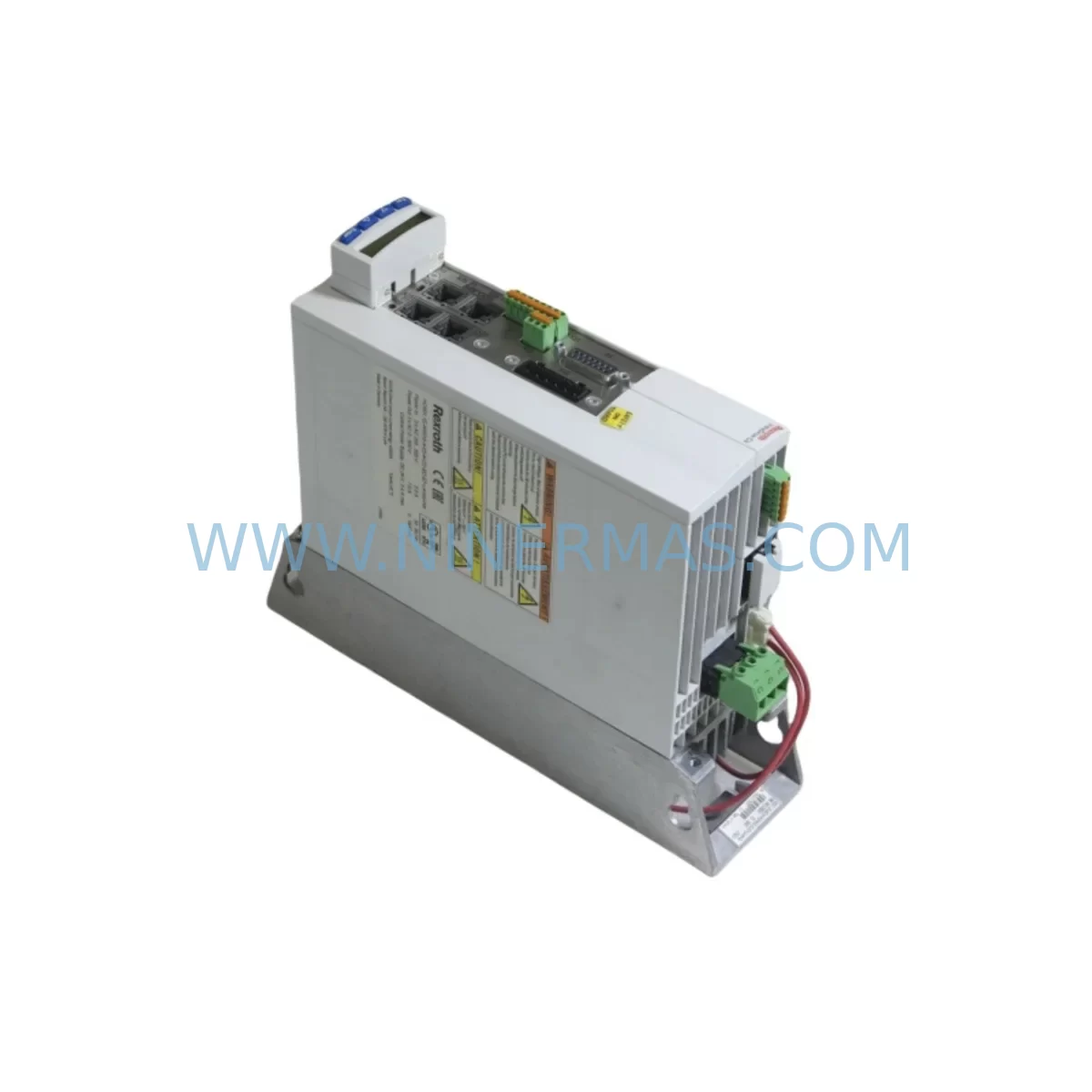
LUST LSG-096-3-30-560/1RB5JZ Retrofit-Compatible Servo Drive for Legacy Systems
Verify the part, confirm the platform family, and move straight into quotation with the right commercial details.
RFQ Ready
- SKULSG-096-3-30-560/1RB5JZ
- CategoryPLC & Industrial Automation Modules
- BrandLUST
- SupportAvailability, lead time, condition, and shipping coordination
How Buyers Usually Use This Page
- Confirm the exact part number and platform family before sending the quote request.
- Use direct email when quantity, condition, and destination are already defined internally.
- Switch to the broader brand or category archive when you need alternates nearby.
Series Navigation
Move through the most common platform families behind this part.
Product RFQ
Send this part directly for quotation.
Include quantity, required condition, destination country, and target delivery timing. Current reference: LUST LSG-096-3-30-560/1RB5JZ Retrofit-Compatible Servo Drive for Legacy Systems with SKU LSG-096-3-30-560/1RB5JZ.
LUST LSG-096-3-30-560/1RB5JZ Retrofit-Compatible Servo Drive for Legacy Systems
The LUST LSG-096-3-30-560/1RB5JZ is a compact, high-performance servo drive from LUST’s LSG series, widely deployed in legacy automation lines across packaging, printing, material handling, and precision motion control applications. As LUST’s LSG product family has reached end-of-life status, plant engineers and maintenance teams face increasing pressure to source verified replacement units that maintain full electrical and functional compatibility with existing control architectures — without triggering a full-system redesign or extended production shutdown.
NINERMAS supplies the LSG-096-3-30-560/1RB5JZ as a direct retrofit-compatible replacement, fully tested prior to shipment and backed by a 12-month warranty. Each unit is inspected for power stage integrity, encoder interface functionality, and communication readiness before dispatch, ensuring your retrofit project starts with a verified, field-ready component.
Upgrade Compatibility Table
| Parameter | LSG-096-3-30-560/1RB5JZ | Retrofit Notes |
|---|---|---|
| Series | LUST LSG | Direct LSG-series replacement for discontinued units |
| Power Supply Input | 3-phase, 30A, 560V DC bus | Verify existing cabinet power capacity before installation |
| Encoder Interface | Incremental / Resolver compatible | Confirm motor feedback type; adapter may be required for SSI or EnDat encoders |
| Communication Protocol | CANopen / PROFIBUS-DP (model-dependent) | Match fieldbus configuration to existing PLC network topology |
| Backplane / Rack Interface | Standalone DIN-rail or panel mount | Confirm mounting rail dimensions and clearance in existing control cabinet |
| Terminal Wiring | Standard screw-terminal block | Re-use existing cable harness; verify terminal pitch compatibility |
| Module Address | Configurable via DIP switch / software | Retain original node address to avoid PLC program changes |
| HMI / Parameter Interface | RS-232 / USB programming port | Use LUST DriveManager or compatible commissioning software |
| Installation Space | Compact form factor | Measure cabinet depth and width before ordering |
| Compatibility Verification | Pre-shipment functional test | All units tested for power stage, encoder interface, and comms readiness |
| Warranty | 12-Month Warranty — all units pre-tested before shipment | |
Retrofit Planning for Existing Automation Systems
Replacing a LUST LSG-096-3-30-560/1RB5JZ in an active production environment requires careful pre-planning across multiple system layers. The servo drive does not operate in isolation — it interfaces with the motor feedback device, the PLC’s motion control module, the fieldbus network, and the HMI operator panel. A structured retrofit approach minimizes risk and reduces commissioning time significantly.
Begin by auditing the existing control cabinet layout. Identify the 24VDC control power supply feeding the drive’s logic board, and confirm that the cabinet’s main power supply — typically a three-phase transformer or rectifier unit — can sustain the LSG-096-3-30-560/1RB5JZ’s rated DC bus voltage of 560V under full load. If the existing power supply is marginal, consider upgrading to a higher-capacity unit during the same maintenance window. In many installations, the LSG drive shares a common DC bus rail with adjacent LSG-series drives or a shared regenerative rectifier module; verify that the B+ and B- bus connections are correctly re-established on the replacement unit.
Next, document the terminal wiring on the existing drive before disconnection. The LSG series uses a standardized screw-terminal layout for analog reference inputs (±10V speed/torque command), digital I/O (enable, fault reset, ready output), and motor power connections (U, V, W phases plus PE). Photograph or sketch the wiring before removal to ensure accurate reconnection on the replacement unit. In many retrofit projects, the existing motor cable — often a shielded four-conductor cable with a separate encoder cable — can be reused directly, provided the cable is in good condition and the connector pinout matches.
For systems using CANopen communication, the replacement drive must be assigned the same node ID as the original unit. This is typically set via DIP switches on the drive’s front panel or through the commissioning software. Failure to match the node ID will cause the PLC — often a Siemens S7-300, S7-400, or equivalent controller — to report a bus fault and halt the motion sequence. Similarly, if the system uses PROFIBUS-DP, the GSD file for the LSG drive must be loaded into the PLC’s hardware configuration tool (e.g., STEP 7 or TIA Portal) to ensure correct parameter mapping.
The motor feedback interface is another critical checkpoint. The LSG-096-3-30-560/1RB5JZ supports incremental encoders and resolver feedback. If the existing motor uses a Hiperface or EnDat absolute encoder, an interface adapter or a firmware parameter change may be required. Confirm the encoder type from the motor nameplate or the original drive’s parameter list before ordering. In multi-axis gantry or winding systems, the LSG drive may also interface with a LUST CDA or CDB compact drive on adjacent axes — ensure that the shared motion profile and electronic gearing parameters are preserved during the replacement.
In systems where the LSG-096-3-30-560/1RB5JZ is installed alongside a LUST power supply module or a shared braking resistor assembly, verify that the braking resistor — often a separate panel-mounted component rated for the drive’s peak regenerative energy — is reconnected to the correct RB+ and RB- terminals on the replacement drive. Oversized or undersized braking resistors will trigger overvoltage faults during deceleration ramps.
For HMI integration, the operator panel — whether a Siemens TP700 Comfort, a Weintek MT8000 series, or a custom panel — communicates drive status via the PLC. In most cases, no HMI screen changes are required if the PLC program and drive parameters are restored correctly. However, if the original drive’s parameter set was stored only in the drive’s internal memory (not backed up to a PC or memory card), the commissioning engineer will need to re-enter all parameters manually using LUST DriveManager software connected via the RS-232 or USB port.
Signal isolators are recommended when the analog reference signal from the PLC’s analog output module travels more than 5 meters to the drive’s command input terminal. A DIN-rail mounted signal isolator — such as a Phoenix Contact MINI Analog or equivalent — prevents ground loop interference that can cause speed instability or fault trips during operation. In I/O-intensive retrofit projects, also verify that the PLC’s digital output module can source sufficient current to drive the LSG’s enable and fault-reset inputs without voltage drop across long cable runs.
Where the retrofit involves migrating from a legacy serial communication protocol to CANopen or PROFIBUS-DP, a protocol gateway or communication bridge module may be required to interface the new drive with an older PLC that lacks native fieldbus support. This is a common scenario when upgrading from older Mitsubishi MELSEC A-series or Omron C200H controllers, where the original drive was controlled via analog ±10V reference rather than a digital fieldbus.
Downtime Control During System Migration
Unplanned downtime during a servo drive replacement is one of the highest-cost risks in industrial maintenance. A well-prepared retrofit of the LUST LSG-096-3-30-560/1RB5JZ can be completed within a planned maintenance window of 4–8 hours, provided all preparatory steps are completed before the line is stopped.
The most effective downtime reduction strategy is parameter backup. Before the old drive fails completely, connect a laptop running LUST DriveManager to the drive’s serial port and export the full parameter set to a file. Store this file in the plant’s maintenance documentation system alongside the wiring diagram and the PLC program backup. When the replacement drive arrives, the parameter file can be uploaded in minutes, eliminating the need for manual re-entry and reducing the risk of commissioning errors.
If the original drive has already failed and no parameter backup exists, the commissioning engineer must reconstruct the parameter set from the motor nameplate data, the machine’s original documentation, and the PLC’s motion control configuration. In this scenario, allow additional time for test runs and fine-tuning of speed loop gains, current limits, and ramp times before returning the machine to production.
To protect the original PLC program logic during the retrofit, do not modify the PLC program unless absolutely necessary. The LSG-096-3-30-560/1RB5JZ is designed to accept the same control signals as the original unit, so the PLC’s motion function blocks — whether written in Structured Text, Ladder Diagram, or Function Block Diagram — should continue to operate without modification. If the PLC is a Siemens S7 series, verify that the FM 353 or FM 354 positioning module’s configuration matches the drive’s axis parameters before restarting the motion sequence.
Maintain field control continuity by keeping the safety relay circuit — typically an emergency stop loop connected to the drive’s STO (Safe Torque Off) input — intact throughout the replacement process. Do not bypass or disconnect the safety circuit during commissioning. Test the E-stop function as the final step before returning the machine to automatic mode. For systems with a safety PLC or a Pilz PNOZ safety relay monitoring the STO channel, confirm that the safety relay’s feedback loop is re-established before the machine is released to operators.
Stock availability is a key factor in downtime control. NINERMAS maintains inventory of LSG-series servo drives to support urgent replacement requirements, with pre-shipment testing completed on every unit. Confirm current stock and lead time with our team before your planned maintenance window to avoid last-minute delays.
Retrofit Support FAQ
Q1: Is the LUST LSG-096-3-30-560/1RB5JZ a direct drop-in replacement for other LSG-series drives?
A: The LSG-096-3-30-560/1RB5JZ is designed as a direct replacement within the LUST LSG series for units with matching power ratings (096 frame, 30A, 560V DC bus). Always verify the original drive’s nameplate data — including current rating, DC bus voltage, and encoder interface type — before ordering. NINERMAS technical support can assist with cross-reference verification prior to purchase.
Q2: What commissioning steps are required after installing the replacement drive?
A: After mechanical installation and wiring, connect LUST DriveManager software via the RS-232 or USB port to upload the saved parameter file. Verify the fieldbus node address, encoder feedback type, and motor nameplate parameters. Perform a low-speed jog test before enabling full-speed automatic operation. Check for fault codes on the drive’s display and confirm the ready output signal is received by the PLC before releasing the machine to production.
Q3: Can the existing motor cable and encoder cable be reused?
A: In most cases, yes. The LSG-096-3-30-560/1RB5JZ uses standard terminal connections for motor power (U, V, W, PE) and a standard encoder connector. Inspect the existing cables for insulation damage, connector wear, and correct shielding before reuse. If the cable has been in service for more than 10 years or shows signs of heat damage, replacement is recommended to avoid intermittent faults after commissioning.
Q4: What does the 12-month warranty cover, and how does NINERMAS handle stock availability?
A: All LUST LSG-096-3-30-560/1RB5JZ units supplied by NINERMAS are covered by a 12-month warranty against manufacturing defects and functional failure under normal operating conditions. Each unit is tested before shipment to verify power stage operation, encoder interface, and communication readiness. NINERMAS maintains stock of LSG-series drives to support urgent replacement requirements. Contact our team for current availability and lead time confirmation before placing your order.
| Product Series | Legacy |
|---|
Catalog Continuation
More LUST modules in the catalog.
Use the brand lane to compare nearby part numbers, platform-adjacent modules, and other inquiry-ready listings before sending your final RFQ.
SKU: SC34.0300.0011.0000.0-JW1 SC34.0300.0011.0000.0
LUST SC34.0300.0011.0000.0-JW1 Service-Ready Spare Part
SKU: CDB32.008.C2.4
LUST CDB32.008.C2.4 Spare Part for Industrial Maintenance
SKU: CDB32.008.W2.2.BR CDB32.008.W2.2.BR.PC1
LUST CDB32.008.W2.2.BR Service-Ready Industrial Spare Part
SKU: SC54.0750.1012.0000.0
LUST SC54-0750-1012-0000-0 Safety-Reliable Servo Drive Module
Catalog Continuation
Alternative parts within PLC & Industrial Automation Modules.
Stay inside the same system family when you need substitutes, adjacent modules, or a broader shortlist for procurement review.