Original Industrial Spare Part
PROVIBTECH TM0180-A08-B00-C15-D10 Retrofit-Compatible Vibration Monitor for Legacy Systems
Verify the part, confirm the platform family, and move straight into quotation with the right commercial details.
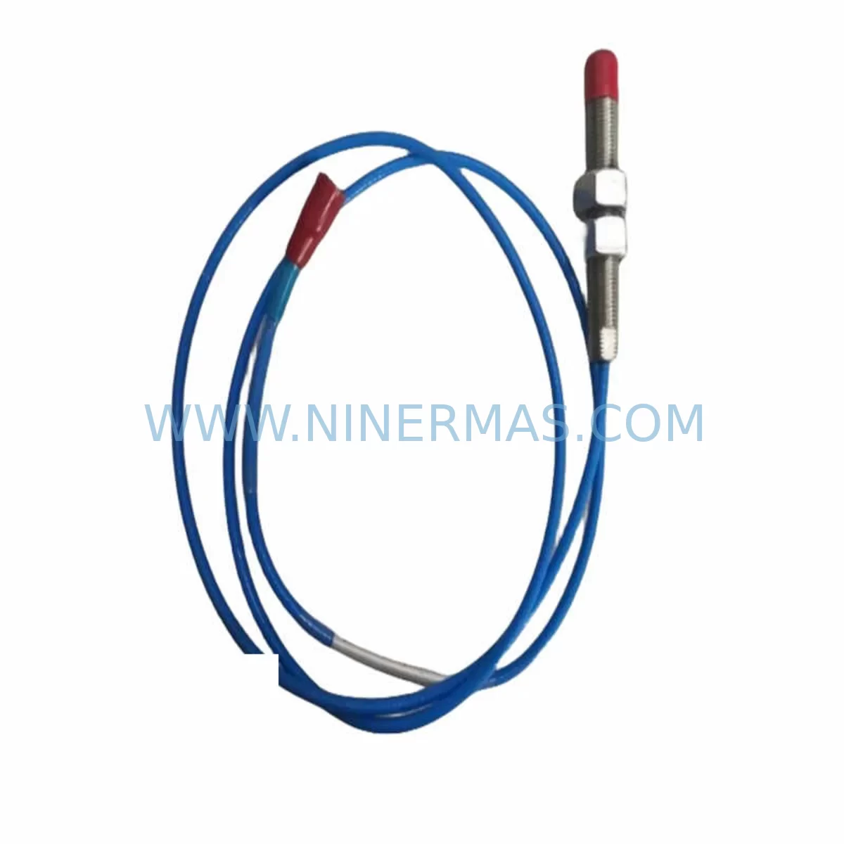
RFQ Ready
- SKUTM0180-A08-B00-C15-D10
- CategoryTSI & Rotating Machinery Monitoring
- BrandProvibTech
- SupportAvailability, lead time, condition, and shipping coordination
How Buyers Usually Use This Page
- Confirm the exact part number and platform family before sending the quote request.
- Use direct email when quantity, condition, and destination are already defined internally.
- Switch to the broader brand or category archive when you need alternates nearby.
Series Navigation
Move through the most common platform families behind this part.
Product RFQ
Send this part directly for quotation.
Include quantity, required condition, destination country, and target delivery timing. Current reference: PROVIBTECH TM0180-A08-B00-C15-D10 Retrofit-Compatible Vibration Monitor for Legacy Systems with SKU TM0180-A08-B00-C15-D10.
PROVIBTECH TM0180-A08-B00-C15-D10: Retrofit-Compatible Vibration Monitor for Legacy Automation Systems
The PROVIBTECH TM0180-A08-B00-C15-D10 is a precision vibration monitoring module engineered for seamless integration into existing industrial control architectures. As legacy condition monitoring systems approach end-of-life and original spare parts become increasingly scarce, the TM0180-A08-B00-C15-D10 provides a validated retrofit path that preserves your existing wiring infrastructure, sensor inputs, and control cabinet layout while delivering modern signal processing performance. Whether you are managing a planned upgrade cycle or responding to an unplanned failure of a discontinued vibration transmitter, this module is stocked and ready for immediate dispatch with a 12-month warranty.
Designed for rotating machinery protection in turbines, compressors, pumps, fans, and gearboxes, the TM0180-A08-B00-C15-D10 accepts standard eddy-current proximity probe inputs and velocity transducer signals. Its configurable channel parameters — encoded in the part number suffix A08-B00-C15-D10 — define the measurement range, buffered output voltage, alarm relay configuration, and power supply input, making it a direct functional replacement for earlier TM0180 variants that may no longer be available through the original manufacturer’s distribution network.
Upgrade Compatibility Table
| Parameter | TM0180-A08-B00-C15-D10 | Retrofit Notes |
|---|---|---|
| Input Signal Type | Eddy-current / Velocity Transducer | Compatible with existing Bently Nevada 3300 series probes and equivalent sensors; no re-cabling required in most installations |
| Power Supply Input | 24 VDC (D10 suffix) | Verify existing cabinet PSU output; compatible with standard 24 VDC DIN-rail power supplies such as SITOP PSU100S or equivalent |
| Output Configuration | 4–20 mA / Buffered BNC (C15) | Confirm DCS or PLC analog input card range; 4–20 mA loop wiring can be reused directly |
| Alarm Relay | B00 — Relay output configurable | Map relay contacts to existing DCS alarm input terminals; verify NC/NO logic before energising |
| Mounting / Form Factor | DIN-rail or panel-mount | Confirm available rail space in control cabinet; standard 35 mm DIN rail compatible |
| Communication Protocol | Analogue (4–20 mA); optional RS-485 Modbus RTU | If migrating to digital bus, add a Modbus RTU-to-Ethernet gateway module to preserve existing HMI screen data mapping |
| Replacement Scope | Direct drop-in for TM0180 series variants | Cross-reference legacy part numbers TM0180-A08-B00-C10-D10 and TM0180-A08-B00-C15-D05 for parameter alignment |
| Commissioning Requirement | Zero-point calibration + alarm setpoint verification | Use original calibration records; re-enter gap voltage and scale factor via front-panel DIP switches or configuration software |
| Warranty | 12-Month Warranty — covers manufacturing defects; includes pre-shipment functional test report | |
Retrofit Planning for Existing Automation Systems
A successful retrofit of the TM0180-A08-B00-C15-D10 into a legacy condition monitoring rack begins well before the module arrives on site. The first step is a thorough audit of the existing control cabinet: confirm the available 24 VDC supply capacity from the installed DIN-rail power supply — if the cabinet already runs a SITOP PSU100S or a Phoenix Contact QUINT-PS, verify that adding the TM0180 module does not exceed the rated output current. In older installations where the power supply itself is approaching end-of-life, it is advisable to replace it concurrently to avoid a secondary failure during the commissioning window.
Terminal wiring is the next critical checkpoint. The TM0180-A08-B00-C15-D10 uses a standard screw-terminal block for sensor input, power, and output connections. Before disconnecting the legacy module, photograph and document every terminal assignment. In many legacy racks, the vibration monitor shares a common terminal strip with nearby modules such as a TM0182 temperature monitor or a TM0160 speed monitor — both of which may be candidates for concurrent replacement if they share the same discontinued product family. Confirm that the terminal numbering on the replacement module matches the existing field wiring layout; if it does not, prepare a terminal adapter or re-label the wiring harness before the planned outage window.
For installations where the TM0180 feeds a 4–20 mA signal into a legacy PLC analog input card — such as a Siemens S7-300 SM331 or an Allen-Bradley 1746-NI4 — verify the input impedance and loop supply voltage compatibility. If the control system has already been migrated to a newer platform such as a Siemens S7-1500 or a Rockwell ControlLogix, confirm that the new analog input module’s resolution and filtering settings are configured to match the original alarm setpoints stored in the PLC program. Failure to align these parameters can result in nuisance trips or, more critically, missed alarms during the post-retrofit run-in period.
Where the vibration data is displayed on an HMI — whether a Siemens TP700 Comfort Panel, a Weintek cMT series, or a legacy Proface GP series — review the screen tag database to confirm that the analog input address and engineering unit scaling remain consistent after the module swap. If the original module used a buffered BNC output to drive a portable data collector or a permanently installed spectrum analyser, verify that the C15 buffered output on the TM0180-A08-B00-C15-D10 delivers the same voltage range and impedance as the legacy unit.
In installations where the vibration monitor communicates over an RS-485 Modbus RTU network — common in older SCADA architectures — confirm the device address, baud rate, and parity settings before powering up the replacement module. If the legacy module used a proprietary communication protocol, a Modbus RTU-to-Ethernet gateway or a protocol converter may be required to bridge the gap between the TM0180’s standard interface and the plant’s existing data highway. This is particularly relevant in facilities that are mid-migration from a legacy DCS to a modern distributed I/O architecture using EtherNet/IP or PROFINET.
Finally, confirm the physical installation space. The TM0180-A08-B00-C15-D10 is designed for 35 mm DIN-rail mounting, but in older panel-mount racks, the available depth and width may be constrained by adjacent modules such as signal isolators, relay output modules, or surge protection barriers. Measure the available slot width and confirm that the module’s depth does not conflict with cable management channels or backplane connectors. If the legacy rack uses a proprietary backplane — as found in some older Bently Nevada 3500 series racks — a standalone DIN-rail sub-panel may need to be fabricated to house the replacement module within the existing cabinet footprint.
Downtime Control During System Migration
Minimising unplanned downtime is the primary operational constraint in any vibration monitor replacement project. The recommended approach is to pre-configure and bench-test the TM0180-A08-B00-C15-D10 before the scheduled maintenance window. Using the module’s configuration software or front-panel DIP switches, pre-enter the gap voltage setpoint, full-scale measurement range, alarm trip level, and 4–20 mA output scaling based on the original calibration records. This eliminates the need for iterative on-site adjustment during the outage and reduces the commissioning window to a straightforward swap-and-verify sequence.
During the outage, follow a structured isolation procedure: de-energise the sensor loop, disconnect the field wiring at the terminal block, remove the legacy module, install the TM0180-A08-B00-C15-D10, reconnect the field wiring in the documented sequence, and restore power. Before returning the machine to service, perform a static verification: apply a known reference signal to the sensor input — using a portable eddy-current calibrator or a signal simulator — and confirm that the module’s output, alarm relay state, and any Modbus register values match the expected values from the pre-commissioning bench test.
To protect the original PLC program logic, do not modify any ladder logic, function block, or structured text routines during the module replacement. The goal is a transparent hardware swap: the PLC should see the same analog input values and alarm contact states as it did with the legacy module. If the replacement module introduces any offset in the 4–20 mA output due to calibration differences, correct this at the module level — not in the PLC program — to preserve the integrity of the original control logic and avoid unintended interactions with interlocked systems such as emergency shutdown sequences or variable-speed drive control loops.
For critical machinery where continuous monitoring is required, consider a parallel-run strategy: install the TM0180-A08-B00-C15-D10 alongside the legacy module using a signal splitter or a dual-output sensor, and compare the readings over a 24–48 hour period before fully decommissioning the old unit. This approach is particularly valuable in applications where the vibration monitor feeds a safety instrumented system (SIS) or a machinery protection system that requires a validated proof-test before the new module is accepted into service.
Retrofit Support FAQ
Q1: Is the TM0180-A08-B00-C15-D10 a direct replacement for earlier TM0180 variants with different suffix codes?
A: The TM0180 suffix codes define specific electrical parameters — measurement range (A), relay configuration (B), output type (C), and power supply voltage (D). Variants with the same A and D suffix but different B or C codes can typically be cross-configured using the module’s DIP switch or software settings. Always compare the full suffix code against your legacy module’s datasheet and confirm alarm setpoints, output scaling, and relay logic before installation. NINERMAS can provide a pre-shipment configuration report on request.
Q2: What pre-shipment testing is performed before dispatch?
A: Every TM0180-A08-B00-C15-D10 unit dispatched by NINERMAS undergoes a functional test covering power-up verification, input signal response across the full measurement range, 4–20 mA output linearity check, alarm relay actuation at the configured setpoint, and — where applicable — Modbus RTU register read/write verification. A test report is available upon request and can be included with the shipment documentation.
Q3: What is the warranty coverage and what does it include?
A: All units carry a 12-month warranty from the date of dispatch, covering manufacturing defects in materials and workmanship. The warranty does not cover damage resulting from incorrect installation, overvoltage, or environmental exposure beyond the module’s rated specifications. In the event of a warranty claim, NINERMAS will arrange replacement or repair and can provide a loan unit for critical applications to minimise production downtime.
Q4: How quickly can the TM0180-A08-B00-C15-D10 be shipped, and is long-term stock availability guaranteed?
A: NINERMAS maintains buffer stock of the TM0180-A08-B00-C15-D10 to support emergency breakdown orders and planned maintenance programmes. Standard lead time for in-stock units is 3–5 business days for international shipments. For customers managing multi-year spare parts programmes or lifecycle extension contracts, NINERMAS offers long-term stock commitment agreements to guarantee supply continuity for critical SKUs over a defined procurement horizon. Contact our team to discuss your inventory planning requirements.
| Product Series | Legacy |
|---|
Catalog Continuation
More ProvibTech modules in the catalog.
Use the brand lane to compare nearby part numbers, platform-adjacent modules, and other inquiry-ready listings before sending your final RFQ.
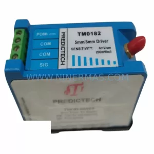
SKU: TM0182-A90-B01-C00
PROVIBTECH TM0182-A90-B01-C00 Safety-Reliable Vibration Monitor
SKU: TM201-A02-B00-C00-000-E00-G00
PROVIBTECH TM201-A02-B00-C00-000-E00-G00 Safety-Reliable Vibration Monitor
Catalog Continuation
Alternative parts within TSI & Rotating Machinery Monitoring.
Stay inside the same system family when you need substitutes, adjacent modules, or a broader shortlist for procurement review.
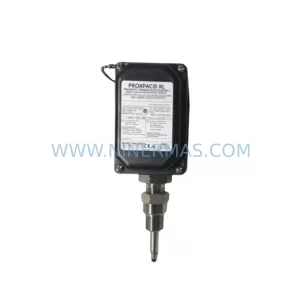
SKU: 330880-16-15-020-01-02
Bently Nevada 330880-16-15-020-01-02 Service-Ready Spare Part
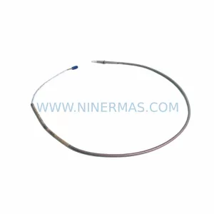
SKU: 330910-00-13-10-02-05
Bently Nevada 330910-00-13-10-02-05 Safety-Reliable Proximity Transducer
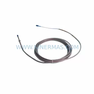
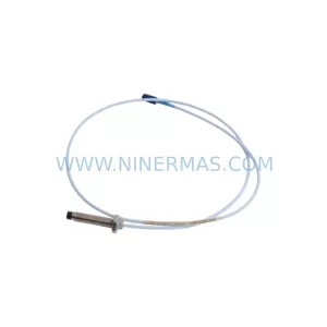
SKU: 330103-00-10-10-11-05
Bently Nevada 330103-00-10-10-11-05 Safety Proximity Transducer