Original Industrial Spare Part
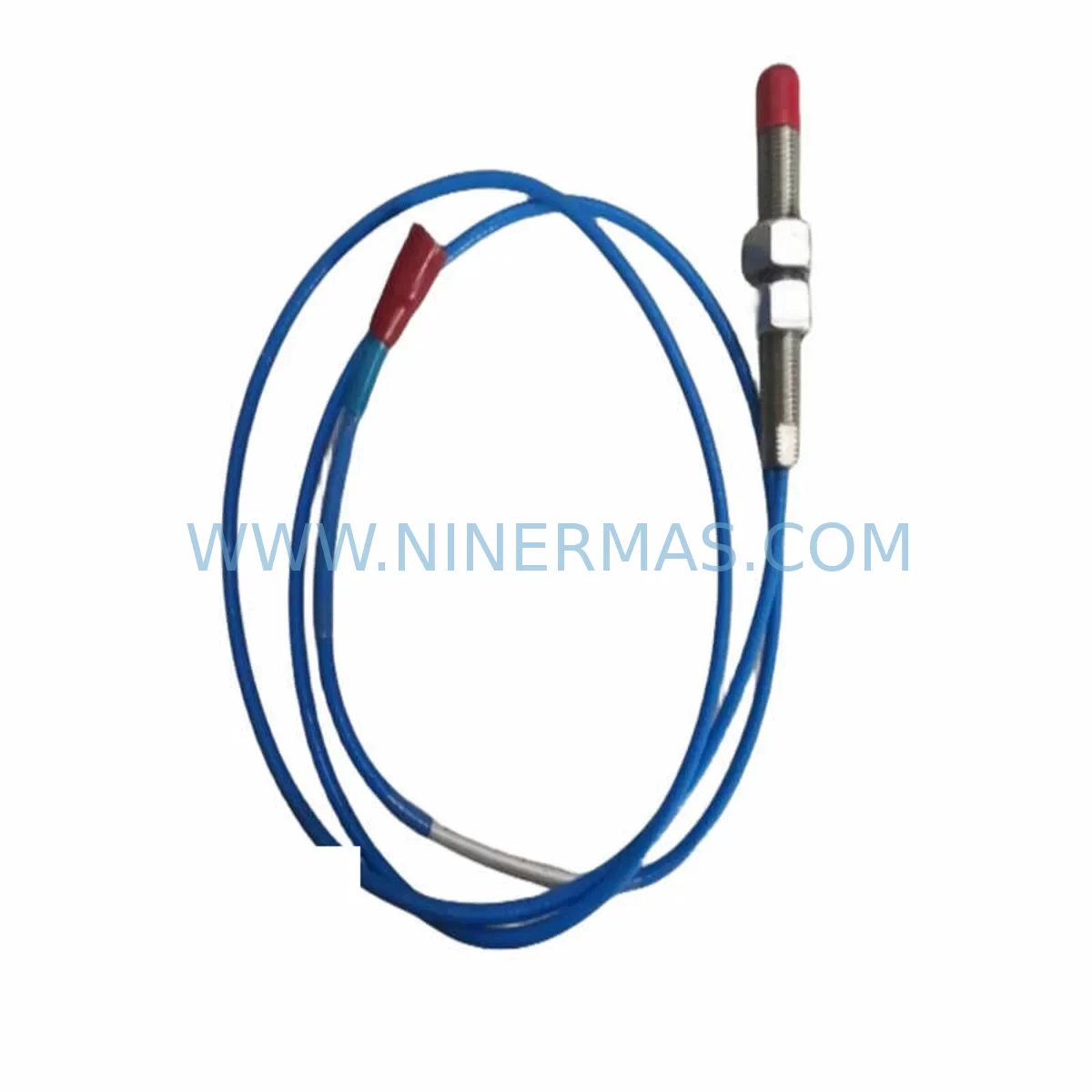
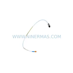
PROVIBTECH TM0180-A07-B00-C05-D10 Spare Extension Cable
Verify the part, confirm the platform family, and move straight into quotation with the right commercial details.
RFQ Ready
- SKUTM0180-A07-B00-C05-D10
- CategoryTSI & Rotating Machinery Monitoring
- BrandProvibTech
- SupportAvailability, lead time, condition, and shipping coordination
How Buyers Usually Use This Page
- Confirm the exact part number and platform family before sending the quote request.
- Use direct email when quantity, condition, and destination are already defined internally.
- Switch to the broader brand or category archive when you need alternates nearby.
Series Navigation
Move through the most common platform families behind this part.
Product RFQ
Send this part directly for quotation.
Include quantity, required condition, destination country, and target delivery timing. Current reference: PROVIBTECH TM0180-A07-B00-C05-D10 Spare Extension Cable with SKU TM0180-A07-B00-C05-D10.
PROVIBTECH TM0180-A07-B00-C05-D10 Service-Ready Spare Extension Cable for Industrial Maintenance
The PROVIBTECH TM0180-A07-B00-C05-D10 is a ruggedized extension cable module engineered for continuous-duty vibration monitoring applications in harsh industrial environments. Designed to interface directly with PROVIBTECH eddy-current proximity probe systems, this cable serves as a critical signal transmission link between the proximity probe tip and the signal conditioner or vibration monitor. When a cable fault, signal degradation, or physical damage occurs on the production floor, having a verified spare of the TM0180-A07-B00-C05-D10 on hand is the fastest path to restoring measurement integrity and resuming normal operations.
Maintenance engineers working on rotating machinery protection systems — including steam turbines, gas compressors, centrifugal pumps, and large induction motors — rely on this extension cable to maintain the precise gap voltage and sensitivity required by the overall proximity probe chain. The TM0180 series follows a modular configuration logic: the A07 designator specifies the cable body type, B00 indicates the connector termination style, C05 defines the cable length (5 metres), and D10 identifies the impedance and sensitivity matching group. Any replacement must match all four parameters to preserve system calibration and avoid false trip signals or missed fault detection.
From a procurement and inventory planning perspective, the TM0180-A07-B00-C05-D10 is a consumable-class spare that should be stocked at a minimum ratio of one spare per three installed units. Cable failures in vibration monitoring circuits are among the most common causes of nuisance trips and unplanned shutdowns in rotating equipment protection systems. Proactive stocking eliminates the lead-time risk associated with sourcing specialty instrumentation cables during an active outage.
Spare Maintenance Table
| Parameter | Specification / Recommendation |
|---|---|
| SKU | TM0180-A07-B00-C05-D10 |
| Brand / Series | PROVIBTECH / TM0180 |
| Product Type | Ruggedized Extension Cable Module |
| Cable Length | 5 metres (C05 designation) |
| Connector Type | B00 — standard coaxial termination |
| Sensitivity Group | D10 — matched to TM0180 probe/driver system |
| Operating Temperature | -40°C to +125°C (typical for TM0180 series) |
| Application | Rotating machinery vibration monitoring, proximity probe chains |
| Compatibility | PROVIBTECH TM0180 proximity probes and signal conditioners |
| Installation Requirement | Match probe tip, extension cable, and driver as a calibrated set |
| Maintenance Interval | Inspect annually or after any mechanical disturbance near cable routing |
| Warranty | 12 Months from date of shipment |
Maintenance Planning for Continuous Operation
When scheduling a replacement of the TM0180-A07-B00-C05-D10 extension cable, maintenance engineers should treat the intervention as an opportunity to audit the entire proximity probe measurement chain. The extension cable does not operate in isolation — it is the middle link between the TM0180 proximity probe tip and the TM0180 signal conditioner or driver module mounted in the instrument rack or control cabinet.
Begin by verifying the condition of the proximity probe itself. If the TM0180 probe tip shows signs of physical damage, corrosion at the tip face, or a shift in the static gap voltage reading, replacing only the extension cable will not restore measurement accuracy. In many field cases, the probe tip and extension cable are replaced together as a matched set to maintain factory calibration. The driver module — typically a TM0180-series signal conditioner — should also be checked for output voltage stability, as a degraded driver can mask cable faults or produce erratic vibration readings even after a cable swap.
Inside the control cabinet, inspect the terminal blocks and signal wiring that connect the driver output to the vibration monitor or protection relay. Loose terminations on DIN-rail mounted terminal strips are a frequent source of intermittent signal loss that is often misdiagnosed as a cable fault. If the plant uses a Bently Nevada 3500 series or similar third-party vibration monitoring rack, confirm that the input channel card is configured for the correct probe sensitivity (typically 7.87 V/mm or 200 mV/mil for standard eddy-current systems) before reconnecting the replacement cable.
For plants running a distributed control system (DCS) or safety instrumented system (SIS) that receives vibration signals from the proximity probe chain, coordinate the cable replacement with the control room to place the affected channel in bypass or maintenance override mode. This prevents a nuisance trip on the high-vibration protection logic during the reconnection and gap-setting procedure. After installation, perform a static gap voltage check using a calibrated digital multimeter — the target gap voltage for most TM0180 configurations is in the -10 VDC to -18 VDC range depending on the probe-to-target gap distance.
Additional components that should be inspected or staged as part of a comprehensive maintenance kit include: the coaxial cable connector and locking nut at both the probe and driver ends, any signal isolator modules used to break ground loops between the field instrument and the DCS analog input card, the 24 VDC or ±15 VDC power supply feeding the driver module, and any surge protection devices installed on the signal cable entry into the control cabinet. If the plant uses a PLC-based monitoring solution, verify that the analog input module (AI card) is reading within the expected voltage range after the cable replacement is complete.
Site Replacement Workflow
A structured on-site replacement of the TM0180-A07-B00-C05-D10 minimises downtime and reduces the risk of introducing new faults during the intervention. Follow this sequence to ensure a safe, calibrated, and documented replacement:
Step 1 — Preparation and Isolation: Obtain a work permit and confirm the machinery is in a safe state for instrumentation work. Place the affected vibration channel in bypass at the protection system. Gather the replacement TM0180-A07-B00-C05-D10 cable, a calibrated multimeter, and the original probe installation drawing showing the required gap distance.
Step 2 — Disconnection: Disconnect the extension cable at both ends — at the probe tip connector and at the driver module input. Label the driver module terminals before disconnecting to avoid wiring errors on reconnection. Inspect the connector threads and O-rings for wear; replace if damaged.
Step 3 — Installation: Route the new TM0180-A07-B00-C05-D10 cable following the original cable path. Avoid sharp bends below the minimum bend radius and keep the cable away from high-voltage power cables to prevent electromagnetic interference. Secure the cable with appropriate cable clamps at the same intervals as the original installation.
Step 4 — Gap Setting and Verification: Reconnect the cable at both ends and power up the driver module. Measure the static gap voltage at the driver output. Adjust the probe-to-shaft gap as required to achieve the target voltage specified in the system documentation. Record the final gap voltage in the maintenance log.
Step 5 — Functional Test and Release: Remove the bypass from the protection system and confirm that the vibration channel is reading a stable, plausible value. Check for alarm or trip conditions. If the reading is stable and within normal operating range, close out the work permit and update the spare parts inventory record.
Spare Parts Support FAQ
Q1: Is the TM0180-A07-B00-C05-D10 a direct drop-in replacement for the original installed cable?
Yes, provided the replacement cable carries the identical part number TM0180-A07-B00-C05-D10. The four-segment code (A07-B00-C05-D10) defines the cable body, connector, length, and sensitivity group as a matched set. Substituting a cable with a different length (e.g. C08 for 8 metres) or a different sensitivity group (e.g. D08) will alter the system calibration and may require re-gapping and re-commissioning of the entire probe chain.
Q2: How is the cable tested before shipment?
Each TM0180-A07-B00-C05-D10 unit is subject to continuity, insulation resistance, and impedance verification prior to packaging. Units are shipped with individual test records available on request. The 12-month warranty covers manufacturing defects and electrical performance failures under normal operating conditions.
Q3: What is the recommended inventory strategy for this cable?
For critical rotating machinery applications, we recommend maintaining a minimum of one spare TM0180-A07-B00-C05-D10 per three installed units, with a reorder trigger set at the last spare. For plants with extended lead-time risk (remote locations, single-source procurement), a two-spare buffer per machine train is advisable. Long-term supply agreements are available for customers with multi-site or multi-unit requirements.
Q4: Can NINERMAS supply this cable for legacy systems where the original PROVIBTECH documentation is unavailable?
Yes. Our technical team can cross-reference the TM0180-A07-B00-C05-D10 against installed system configurations using the probe tip model, driver module model, and measured gap voltage. Contact us with your system details and we will confirm compatibility before shipment. All units are supplied with a 12-month warranty and full traceability documentation.
| Product Series | Other series |
|---|
Catalog Continuation
More ProvibTech modules in the catalog.
Use the brand lane to compare nearby part numbers, platform-adjacent modules, and other inquiry-ready listings before sending your final RFQ.
SKU: TM0182-A50-B01-C00
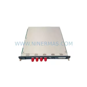
PROVIBTECH TM0182-A50-B01-C00 Retrofit Vibration Monitor
SKU: TM0180-A08-B00-C10-D05
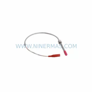
PROVIBTECH TM0180-A08-B00-C10-D05 Retrofit Extension Cable
SKU: TM0180-A08-B13-C20-D10
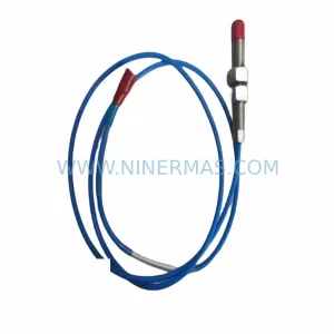
PROVIBTECH TM0180-A08-B13-C20-D10 Retrofit Proximity Probe
Catalog Continuation
Alternative parts within TSI & Rotating Machinery Monitoring.
Stay inside the same system family when you need substitutes, adjacent modules, or a broader shortlist for procurement review.
SKU: 330104-00-13-50-02-00
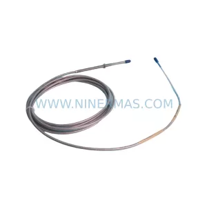
Bently Nevada 330104-00-13-50-02-00 Retrofit-Compatible Proximity Transducer
SKU: 33105-02-12-05-02-00
Bently Nevada 33105-02-12-05-02-00 Safety-Reliable Probe