Original Industrial Spare Part
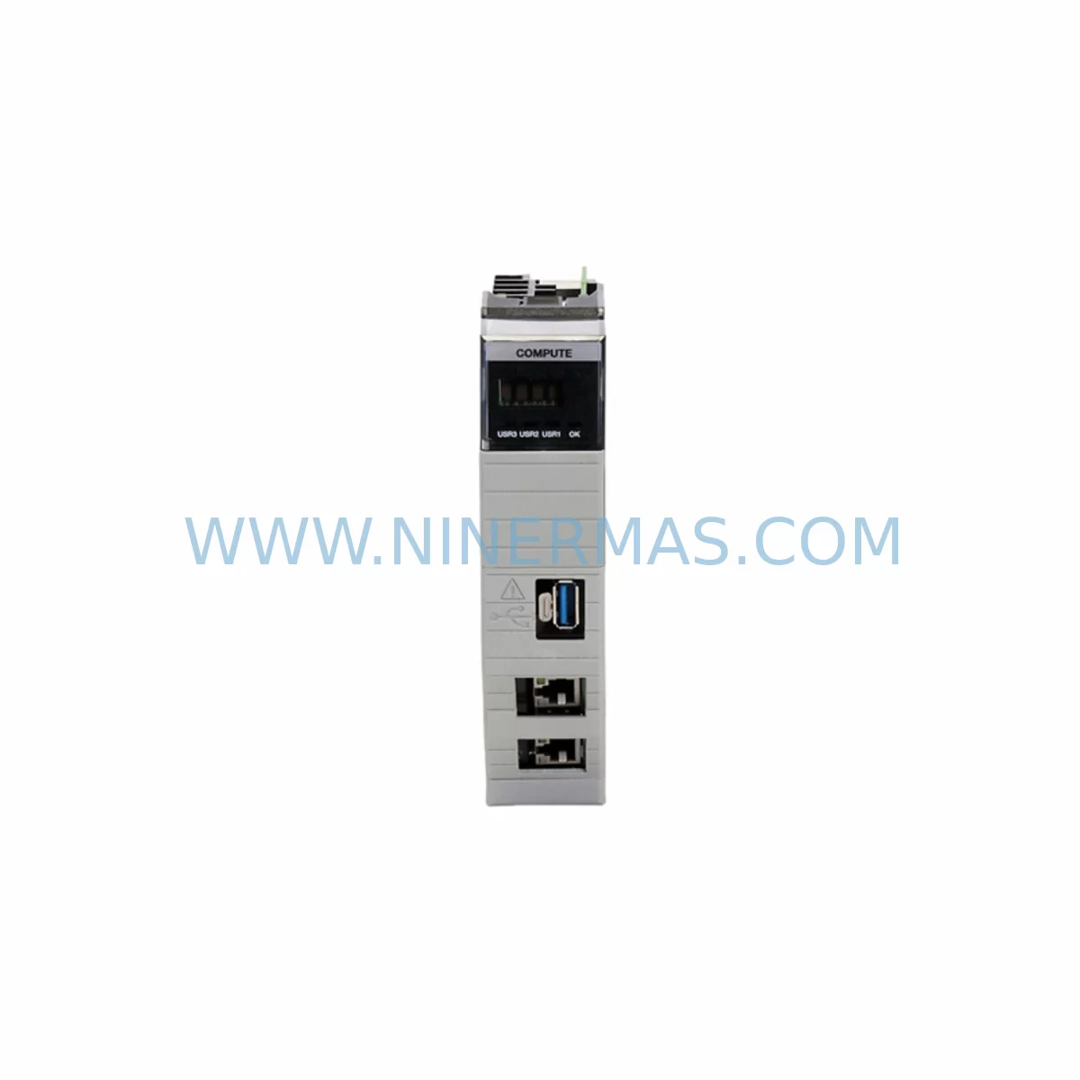
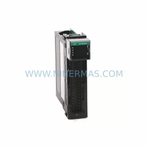
Allen-Bradley 1756-CMS1B1 Retrofit-Compatible Media for Legacy Systems
Verify the part, confirm the platform family, and move straight into quotation with the right commercial details.
RFQ Ready
- SKU1756-CMS1B1
- CategoryPLC & Industrial Automation Modules
- BrandAllen-Bradley
- SupportAvailability, lead time, condition, and shipping coordination
How Buyers Usually Use This Page
- Confirm the exact part number and platform family before sending the quote request.
- Use direct email when quantity, condition, and destination are already defined internally.
- Switch to the broader brand or category archive when you need alternates nearby.
Series Navigation
Move through the most common platform families behind this part.
Product RFQ
Send this part directly for quotation.
Include quantity, required condition, destination country, and target delivery timing. Current reference: Allen-Bradley 1756-CMS1B1 Retrofit-Compatible Media for Legacy Systems with SKU 1756-CMS1B1.
Allen-Bradley 1756-CMS1B1 Retrofit-Compatible Media for Legacy Systems
The Allen-Bradley 1756-CMS1B1 is a ControlLogix-platform compact flash media module designed to store controller firmware, program logic, and configuration data for Rockwell Automation’s 1756 chassis-based control systems. As legacy ControlLogix installations age and original media modules reach end-of-life, the 1756-CMS1B1 has become a critical spare part for engineers managing retrofit projects, system upgrades, and unplanned downtime recovery across manufacturing, oil & gas, water treatment, and discrete automation environments.
At NINERMAS, we maintain verified in-stock inventory of the 1756-CMS1B1 to support procurement teams, system integrators, and plant engineers who require fast, reliable access to discontinued or hard-to-source ControlLogix components. Every unit ships with a 12-month warranty and undergoes pre-shipment functional verification to ensure compatibility with your existing control architecture.
Upgrade Compatibility Table
| Parameter | 1756-CMS1B1 Specification | Retrofit Notes |
|---|---|---|
| Module Type | Compact Flash Media Module | Direct replacement for legacy 1756-CMS1 variants |
| Platform Compatibility | ControlLogix 1756 Chassis | Compatible with 1756-L6x and 1756-L7x controller families |
| Storage Capacity | 1 GB Compact Flash | Sufficient for full program backup and firmware image |
| Installation Interface | Compact Flash slot on 1756-Lxx controller front panel | No backplane slot required; tool-free insertion |
| Communication Compatibility | N/A (storage media) | Works alongside 1756-EN2T, 1756-ENBT EtherNet/IP modules |
| Firmware Support | Stores RSLogix 5000 / Studio 5000 project files | Verify firmware version matches target controller revision |
| Replacement Path | Replaces 1756-CMS1, 1756-CMS1A | Confirm controller slot addressing before swap |
| Commissioning Requirement | Load program via controller web server or RSLinx | Backup existing flash before removal |
| Warranty | 12-Month Warranty — All units tested prior to shipment | |
Retrofit Planning for Existing Automation Systems
When planning a retrofit around the 1756-CMS1B1, the starting point is always a thorough audit of the existing ControlLogix chassis configuration. A typical legacy installation may include a 1756-L61 or 1756-L63 controller paired with a 1756-A10 or 1756-A17 chassis backplane, populated with a mix of 1756-IB16 digital input modules, 1756-OB16E digital output modules, and 1756-IF8 analog input modules. Understanding the slot addressing and I/O tree structure in the existing RSLogix 5000 project is essential before any media swap is attempted.
The 1756-CMS1B1 stores the controller’s program image and firmware. Before removal of the old media, engineers should export a full project backup via Studio 5000 Logix Designer and verify the backup against the live controller using the compare utility. This step protects against program loss in the event of a failed restore. If the target controller is a 1756-L71 or 1756-L73, confirm that the firmware revision stored on the replacement 1756-CMS1B1 matches the controller’s current firmware to avoid a forced firmware update cycle during commissioning.
In systems where the ControlLogix chassis communicates over EtherNet/IP using a 1756-EN2T or 1756-EN2TR communication module, the network configuration — including IP address, subnet mask, and gateway — is stored in the module itself, not on the compact flash. This means the 1756-CMS1B1 swap does not affect network addressing, simplifying the migration. However, if the system also includes a 1756-DNB DeviceNet bridge module or a 1756-DHRIO Data Highway Plus/Remote I/O module for legacy field device communication, engineers must verify that the program logic referencing those communication paths is intact after the media restore.
For control cabinets that include a 1756-PA72 or 1756-PB72 power supply module, confirm that the chassis power budget accommodates all installed modules before and after the retrofit. Adding or replacing modules during a broader upgrade — such as swapping a legacy 1756-L60M03SE motion controller for a current-generation 1756-L83E — may shift the power draw profile and require a power supply capacity review. The 1756-CMS1B1 itself draws no backplane power, as it is a passive storage device, but the broader retrofit context demands this verification.
If the retrofit scope includes HMI integration, verify that the PanelView Plus 7 or FactoryTalk View SE application references the correct controller tag database. A program restore from the 1756-CMS1B1 will re-establish the tag structure, but any HMI screen that references renamed or reorganized tags will require a corresponding update in the FactoryTalk View project. Coordinate HMI screen validation as part of the commissioning checklist to avoid operator interface errors during startup.
Signal isolation requirements should also be reviewed during the retrofit. If the legacy system uses 1492-AIFM analog interface modules or third-party signal isolators between field transmitters and the 1756-IF8 analog input cards, confirm that the wiring termination and scaling parameters in the restored program match the physical installation. Discrepancies between program scaling and field wiring are a common source of commissioning delays in media-swap retrofits.
For systems that include a 1756-L7SP controller with a 1784-SD2 SD card slot in addition to the compact flash interface, note that the 1756-CMS1B1 occupies the compact flash slot only. The SD card slot remains independent and can be used for additional backup redundancy during the transition period.
Downtime Control During System Migration
Minimizing unplanned downtime during a 1756-CMS1B1 replacement requires a structured pre-outage preparation protocol. Begin by scheduling the swap during a planned maintenance window and communicating the expected outage duration to operations. A straightforward media swap on a 1756-L6x or 1756-L7x controller typically requires 15 to 30 minutes of controller downtime, assuming the replacement media is pre-loaded with the correct firmware and program image.
Before the outage window opens, pre-stage the replacement 1756-CMS1B1 with the verified program image using a bench controller or the ControlLogix firmware upgrade utility. Confirm the firmware revision, program checksum, and I/O configuration match the production system. Having the replacement media ready to insert eliminates the largest variable in downtime duration — program loading time.
During the swap, place the controller in Program mode via RSLinx Classic or Studio 5000 before removing the compact flash. This ensures the controller halts execution cleanly and does not generate a fault log entry that could complicate post-swap diagnostics. After inserting the 1756-CMS1B1, power-cycle the controller and monitor the controller status indicators. A solid green RUN indicator confirms successful program load and execution resume.
For systems with redundant controller configurations using a 1756-RM2 redundancy module, the media swap procedure differs. The primary and secondary controllers must be synchronized before the swap, and the redundancy module must be placed in a controlled switchover state. Consult the ControlLogix Redundancy System User Manual (Publication 1756-UM535) for the specific procedure applicable to your firmware revision. Attempting a media swap on a redundant pair without following the correct sequence can result in an uncontrolled switchover and extended downtime.
Post-swap, verify all I/O modules are communicating correctly by reviewing the I/O tree in Studio 5000 for any inhibited or faulted modules. Confirm that all communication modules — including EtherNet/IP, DeviceNet, and any serial communication modules — have re-established their connections. Run a functional test of critical control loops before returning the system to automatic operation.
Retrofit Support FAQ
Q: Is the 1756-CMS1B1 a direct drop-in replacement for the 1756-CMS1 and 1756-CMS1A?
A: Yes. The 1756-CMS1B1 is the current revision of the ControlLogix compact flash media module and is physically and functionally compatible with all 1756-Lxx controllers that accept compact flash media. No hardware modification is required. Confirm that the firmware image stored on the replacement media matches your controller’s current firmware revision before insertion.
Q: Can I pre-load the 1756-CMS1B1 with my program before the maintenance window?
A: Yes, and this is the recommended approach for minimizing downtime. Use Studio 5000 Logix Designer to save the project to compact flash via a bench controller, or use the controller’s built-in Save to Flash function while the production controller is still online. Verify the saved image by comparing the project file checksum before the swap.
Q: What commissioning steps are required after installing the 1756-CMS1B1?
A: After insertion, power-cycle the controller and confirm the program loads automatically (if the controller is configured for automatic load from flash). Verify the I/O tree shows all modules in a healthy state, confirm communication module connections are re-established, and run a functional test of critical outputs before switching to Run mode. For redundant systems, follow the ControlLogix redundancy switchover procedure.
Q: What does the 12-month warranty cover, and how does NINERMAS handle pre-shipment testing?
A: Every 1756-CMS1B1 unit supplied by NINERMAS is covered by a 12-month warranty against manufacturing defects and functional failure. Prior to shipment, each unit undergoes a pre-shipment functional verification to confirm media integrity and read/write performance. If a unit fails within the warranty period under normal operating conditions, NINERMAS will arrange a replacement. Contact sale@ninermas.com for warranty claims and technical support.
| Product Series | ControlLogix |
|---|---|
| Country of Origin | US |
Catalog Continuation
More Allen-Bradley modules in the catalog.
Use the brand lane to compare nearby part numbers, platform-adjacent modules, and other inquiry-ready listings before sending your final RFQ.
Catalog Continuation
Alternative parts within PLC & Industrial Automation Modules.
Stay inside the same system family when you need substitutes, adjacent modules, or a broader shortlist for procurement review.

SKU: DS200ADPBG1ABB
GE DS200ADPBG1ABB Spare Part for Industrial Maintenance
SKU: TRY/PRG/4-20MA/10-30DC
MOORE TRY/PRG/4-20MA/10-30DC Service-Ready Spare Part