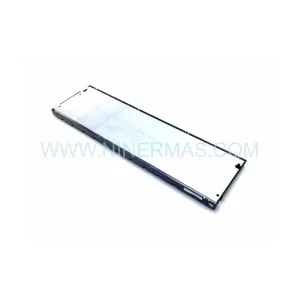
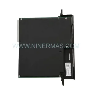
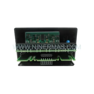
Original Industrial Spare Part
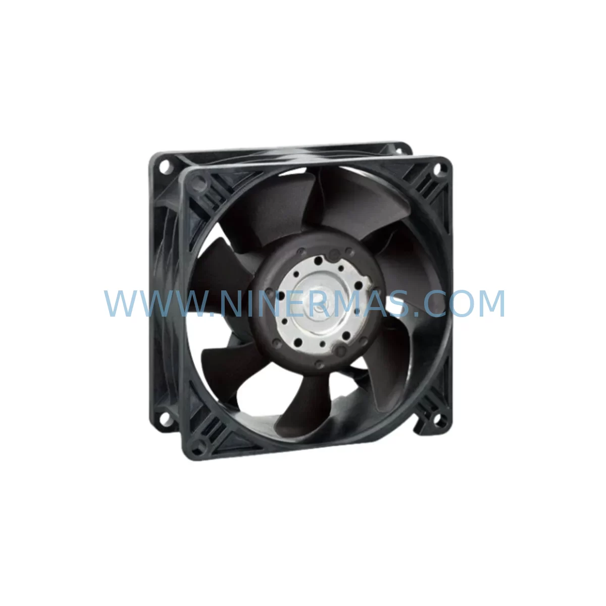
ebmpapst R3G500-RA25-01 Retrofit-Compatible EC Fan for Legacy Systems
Verify the part, confirm the platform family, and move straight into quotation with the right commercial details.
RFQ Ready
- SKUR3G500-RA25-01
- CategoryPLC & Industrial Automation Modules
- Brandebmpapst
- SupportAvailability, lead time, condition, and shipping coordination
How Buyers Usually Use This Page
- Confirm the exact part number and platform family before sending the quote request.
- Use direct email when quantity, condition, and destination are already defined internally.
- Switch to the broader brand or category archive when you need alternates nearby.
Series Navigation
Move through the most common platform families behind this part.
Product RFQ
Send this part directly for quotation.
Include quantity, required condition, destination country, and target delivery timing. Current reference: ebmpapst R3G500-RA25-01 Retrofit-Compatible EC Fan for Legacy Systems with SKU R3G500-RA25-01.
ebmpapst R3G500-RA25-01 Retrofit-Compatible EC Centrifugal Fan for Legacy System Upgrades
The ebmpapst R3G500-RA25-01 is a high-efficiency EC (electronically commutated) centrifugal fan engineered for demanding industrial environments. With its brushless DC motor technology and integrated electronics, this unit is a proven drop-in replacement for aging AC fan assemblies and discontinued centrifugal fan modules across a wide range of industrial control cabinets, power conversion enclosures, and process automation systems. Whether you are managing a planned retrofit or responding to an unplanned failure of an obsolete fan unit, the R3G500-RA25-01 provides a reliable, energy-efficient upgrade path with minimal downtime.
NINERMAS maintains ready stock of the R3G500-RA25-01 to support urgent replacement requirements. All units ship with a 12-month warranty and are subject to pre-shipment functional testing to verify motor operation, speed control response, and electrical integrity before dispatch.
Upgrade Compatibility Table
| Parameter | R3G500-RA25-01 (New) | Typical Legacy AC Fan (Reference) | Retrofit Notes |
|---|---|---|---|
| Fan Type | EC Centrifugal (Backward Curved) | AC Centrifugal / AC Axial | Verify airflow direction and duct interface |
| Motor Technology | Brushless EC (Electronically Commutated) | AC Induction Motor | EC motor requires 1-phase AC input; no separate motor starter needed |
| Input Voltage | 200–277 V AC, 1-phase, 50/60 Hz | 380–415 V AC, 3-phase (typical) | Confirm cabinet power supply capacity and wiring gauge |
| Speed Control Interface | 0–10 V DC analog / PWM / RS-485 (ModBus) | Contactor ON/OFF or VFD analog | Map existing speed reference signal to EC control input; update PLC AO channel scaling if required |
| Mounting / Installation | Flange mount, 500 mm impeller diameter | Varies by OEM frame | Confirm mounting hole pattern, flange dimensions, and available installation depth |
| Communication Protocol | ModBus RTU (RS-485) optional | None / Proprietary | RS-485 wiring to PLC COM port; configure baud rate and node address in drive parameters |
| Thermal Protection | Integrated PTC / electronic overtemperature | External thermal relay | Remove legacy thermal relay from control circuit; map EC fault output to PLC DI |
| Warranty | 12 Months from Date of Shipment — Covered by NINERMAS | ||
Retrofit Planning for Existing Automation Systems
Successful integration of the R3G500-RA25-01 into an existing automation system requires a structured pre-retrofit assessment. The following considerations apply to the most common legacy control architectures encountered in the field.
Power Supply and Cabinet Capacity: The R3G500-RA25-01 draws single-phase AC power, which differs from the three-phase supply typically used by legacy AC fan motors. Before installation, verify that the control cabinet’s single-phase distribution rail has sufficient capacity. If the cabinet uses a Siemens SITOP PSU8600 or similar modular DC power supply for auxiliary circuits, confirm that the 24 V DC control supply feeding the EC fan’s signal electronics is rated for the additional load. In cabinets where a Phoenix Contact QUINT-PS or equivalent DIN-rail power supply is already installed, the 24 V signal wiring for the 0–10 V speed reference can typically be sourced from the same supply rail without modification.
Terminal Wiring and I/O Mapping: The R3G500-RA25-01 uses a compact terminal block connector for power and signal connections. When replacing a legacy fan wired through a Weidmüller WDU 2.5 or Phoenix Contact UK 2.5 terminal block assembly, retain the existing terminal numbering and update the wiring diagram accordingly. The EC fan’s analog speed input (0–10 V) should be connected to the corresponding analog output channel on the PLC — for example, an Allen-Bradley 1756-OF8 ControlLogix analog output module or a Siemens SM 332 analog output module in an S7-300 rack. Confirm that the AO channel is configured for voltage output mode and that the scaling parameters in the PLC program match the fan’s speed curve.
Backplane, Rack, and Module Address Verification: In systems where the fan control logic resides within a Siemens S7-400 or S7-300 rack, verify that the I/O module addresses assigned to the fan control circuit have not shifted due to rack reconfiguration. If the legacy system used a Profibus DP network to communicate fan status, and the new installation uses the R3G500-RA25-01’s RS-485 ModBus interface instead, a Profibus-to-ModBus gateway or a dedicated Siemens CP 342-5 communications processor may be required to bridge the two protocols. Alternatively, if the host PLC supports ModBus RTU natively — as is the case with many Schneider Electric Modicon M340 or M580 controllers — the RS-485 port can be connected directly to the PLC’s serial communications module.
HMI Screen and SCADA Updates: After completing the hardware installation, update the HMI faceplate associated with the fan circuit. If the plant uses a Siemens SIMATIC HMI TP1200 Comfort or a Weintek cMT series panel, revise the fan speed display tag to reflect the new analog scaling (0–100% speed mapped to 0–10 V). Update any alarm setpoints for fan fault, overtemperature, and speed deviation to match the R3G500-RA25-01’s output signal specifications. Where SCADA historians are logging fan speed and power consumption, reconfigure the tag engineering units to align with the EC fan’s reported values.
Communication Link Verification: If ModBus RTU communication is used, verify the RS-485 bus termination resistor placement, confirm the baud rate (default 19200 bps for most ebmpapst EC fans), and perform a register read test using a laptop with a ModBus diagnostic tool before closing the cabinet. This step is critical in multi-drop RS-485 networks where other devices — such as a Danfoss VLT HVAC Drive FC 102 or an ABB ACS880 variable frequency drive — share the same communication bus.
Installation Space Confirmation: The R3G500-RA25-01 has a 500 mm impeller diameter and requires adequate clearance on the inlet and outlet sides. Measure the available installation depth in the cabinet or duct plenum before ordering. In retrofit scenarios where the original fan was a smaller-diameter unit, a transition duct adapter may be required to match the new fan’s flange to the existing ductwork.
Downtime Control During System Migration
Minimizing production downtime during a fan replacement is a primary concern for maintenance engineers. The following approach is recommended for the R3G500-RA25-01 retrofit:
Pre-Staging and Bench Testing: Before the scheduled maintenance window, pre-wire the R3G500-RA25-01 on a bench test rig. Apply rated voltage, connect a 0–10 V signal source, and verify that the fan ramps from minimum to maximum speed without fault. Confirm that the ModBus register map matches the values documented in the ebmpapst datasheet. This eliminates the risk of discovering a wiring or configuration error during the live maintenance window.
Program Logic Preservation: Export and archive the current PLC program before any hardware changes. In Allen-Bradley ControlLogix systems, use Studio 5000 Logix Designer to save an offline copy of the project. In Siemens S7 systems, use TIA Portal or STEP 7 to archive the project with all hardware configuration data. Do not modify the program logic until the new fan is confirmed operational — this allows a rapid rollback to the original configuration if unexpected issues arise.
Phased Cutover: Where process continuity is critical, consider a phased cutover approach: install the R3G500-RA25-01 in parallel with the legacy fan (if physical space permits), verify its operation under load, then switch the control signal over to the new unit and decommission the old fan. This approach is particularly effective in cooling applications where a brief loss of airflow could trigger a thermal shutdown of downstream equipment.
Field Commissioning Checklist: Upon installation, verify supply voltage at the fan terminals, confirm speed reference signal level, check rotation direction, measure motor current at full speed, and confirm fault output signal state. Record all commissioning data for the maintenance log. NINERMAS can provide a commissioning checklist template upon request.
Retrofit Support FAQ
Q1: Is the R3G500-RA25-01 a direct replacement for my existing AC centrifugal fan?
In most cases, yes — provided the mounting flange dimensions and airflow requirements are compatible. The primary difference is the power supply: the R3G500-RA25-01 uses single-phase AC input rather than three-phase. Confirm the electrical specifications against your existing installation before ordering. NINERMAS technical support can assist with compatibility verification.
Q2: What wiring changes are required when replacing a legacy AC fan with the R3G500-RA25-01?
You will need to replace the three-phase power feed with a single-phase supply, remove the external motor starter or contactor, and add a 0–10 V analog signal wire from the PLC analog output to the fan’s speed control input. The fan’s fault output (digital) should be wired to a PLC digital input for alarm monitoring. Full wiring diagrams are available in the ebmpapst technical documentation.
Q3: Does NINERMAS perform pre-shipment testing on the R3G500-RA25-01?
Yes. All units undergo functional testing prior to shipment, including motor run verification, speed control response check, and electrical insulation test. A test record is available upon request. All units are covered by a 12-month warranty from the date of shipment.
Q4: What is the typical lead time and stock availability for the R3G500-RA25-01?
NINERMAS maintains stock of the R3G500-RA25-01 to support urgent replacement requirements. Standard orders ship within 1–3 business days. For large-quantity or project-based orders, contact our sales team to confirm availability and arrange priority allocation.
—
| Product Series | Legacy |
|---|
Catalog Continuation
More ebmpapst modules in the catalog.
Use the brand lane to compare nearby part numbers, platform-adjacent modules, and other inquiry-ready listings before sending your final RFQ.
SKU: R4E355-RM03-05
ebmpapst R4E355-RM03-05 Service-Ready Industrial Spare Part
Catalog Continuation
Alternative parts within PLC & Industrial Automation Modules.
Stay inside the same system family when you need substitutes, adjacent modules, or a broader shortlist for procurement review.
SKU: PFXPP170CA66K00N00
Pro-face PFXPP170CA66K00N00 Service-Ready Spare Part

SKU: 6SL3224-0BE32-2UA0
Siemens 6SL3224-0BE32-2UA0 Retrofit PM240 Power Module