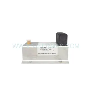
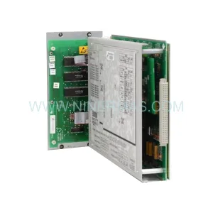
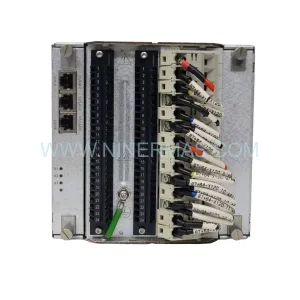
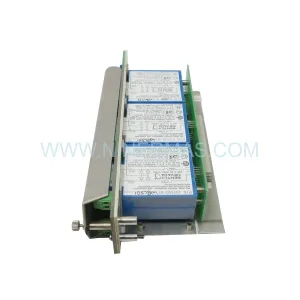
Original Industrial Spare Part
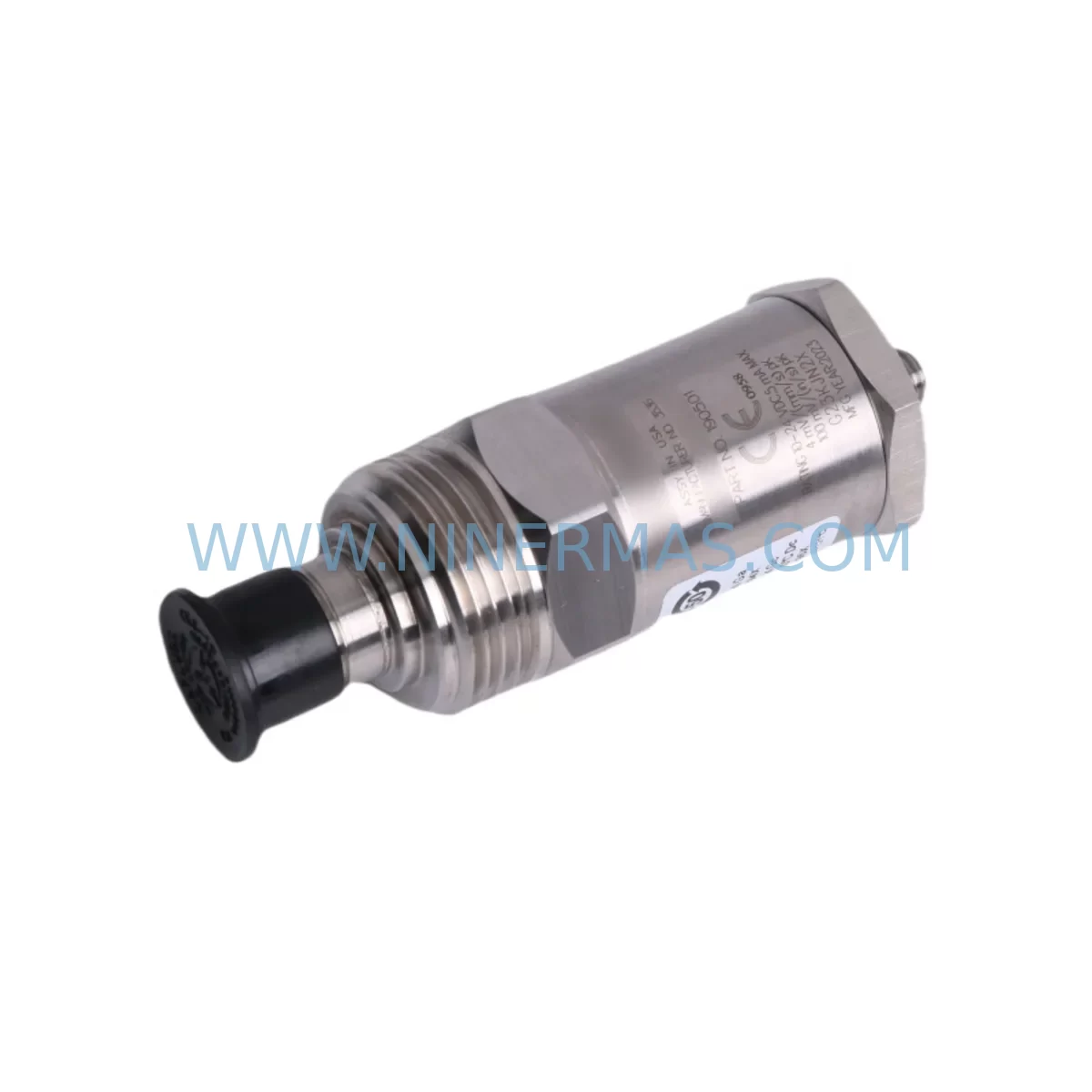
Bently Nevada 190501-23-00-01 Retrofit Velomitor CT
Verify the part, confirm the platform family, and move straight into quotation with the right commercial details.
RFQ Ready
- SKU190501-23-00-01
- CategoryTSI & Rotating Machinery Monitoring
- BrandBently Nevada
- SupportAvailability, lead time, condition, and shipping coordination
How Buyers Usually Use This Page
- Confirm the exact part number and platform family before sending the quote request.
- Use direct email when quantity, condition, and destination are already defined internally.
- Switch to the broader brand or category archive when you need alternates nearby.
Series Navigation
Move through the most common platform families behind this part.
Product RFQ
Send this part directly for quotation.
Include quantity, required condition, destination country, and target delivery timing. Current reference: Bently Nevada 190501-23-00-01 Retrofit Velomitor CT with SKU 190501-23-00-01.
Bently Nevada 190501-23-00-01 Retrofit-Compatible Velomitor CT Transmitter for Legacy Systems
The Bently Nevada 190501-23-00-01 is a Velomitor CT Series piezoelectric velocity transmitter engineered for continuous vibration monitoring on rotating machinery. As original equipment reaches end-of-life and spare parts become increasingly scarce, the 190501-23-00-01 serves as a proven retrofit solution for facilities operating legacy Bently Nevada monitoring architectures — including older 3300 Series and 3500 Series rack-based systems — where maintaining measurement continuity without full platform replacement is the priority.
This transmitter delivers a 4–20 mA output signal proportional to vibration velocity, making it directly compatible with existing signal conditioning infrastructure. Its compact, hermetically sealed housing is designed for direct field installation on bearing housings, gearboxes, pump casings, compressor frames, and motor end-bells, with no modification to existing mounting pads or conduit runs in most retrofit scenarios.
Upgrade Compatibility Table
| Parameter | 190501-23-00-01 (This Unit) | Retrofit Notes |
|---|---|---|
| Output Signal | 4–20 mA (velocity proportional) | Compatible with existing 3300/3500 I/O modules; no signal conditioner swap required in most cases |
| Mounting Interface | 1/4-28 UNF threaded stud | Matches standard Velomitor CT mounting footprint; verify pad thread condition before installation |
| Cable Connector | 2-pin MIL-spec connector | Confirm existing field cable pinout; adapter cables available for older installations |
| Supply Voltage | 18–30 VDC (loop powered) | Verify rack power supply capacity — 3500/20 Power Supply or equivalent must support added loop current |
| Communication Protocol | Analog 4–20 mA (passive loop) | No protocol migration required; integrates directly into existing DCS or safety system analog input cards |
| Operating Temperature | –50°C to +121°C | Suitable for high-temperature bearing locations; confirm local ambient against original sensor rating |
| Installation Space | Compact inline body | No additional panel or rack space required; field-mounted only |
| Replacement Relationship | Direct replacement for discontinued Velomitor CT variants | Cross-reference original tag number and wiring diagram before removal |
| Warranty | 12-Month Warranty — covers manufacturing defects and functional performance from date of shipment | |
Retrofit Planning for Existing Automation Systems
Successful integration of the 190501-23-00-01 into a running plant begins well before the sensor arrives on site. Maintenance engineers should pull the original loop wiring diagram and confirm the field cable pair terminations at both the junction box and the 3500 Series monitor rack. The 3500/42M Proximitor/Seismic Monitor or 3500/40M Proximitor Monitor — whichever governs the affected measurement point — must be checked for its configured full-scale range and alarm setpoints, since a direct sensor swap preserves these parameters without requiring a monitor reconfiguration in most cases.
Power budget verification is a critical pre-installation step. The 3500/20 Power Supply module feeding the affected rack must have sufficient headroom to support the 190501-23-00-01 loop current in addition to all other connected transmitters and I/O modules. If the rack is near capacity, a supplemental 3500/20 or an external 24 VDC DIN-rail power supply may be required before the retrofit proceeds.
For facilities that have already migrated portions of their monitoring infrastructure to the System 1 Evolution software platform, the 190501-23-00-01 analog output integrates cleanly through existing 3500 rack I/O without requiring any System 1 configuration changes, provided the measurement point database entry retains the original engineering unit scaling. Engineers should verify the System 1 trend historian is logging the correct tag after sensor replacement and confirm that no gap in the vibration trend record will trigger a false alarm condition in the DCS or safety instrumented system.
Where the legacy installation includes a 3300/16 Dual Velocity Monitor or a standalone 3300/55 Dual Velocity Monitor, the 190501-23-00-01 can replace the field sensor while the monitor module itself remains in service, extending the useful life of the rack assembly without requiring a full 3500 Series migration. This approach is particularly valuable in control cabinets where available rack slots are limited and a full platform upgrade would require significant panel re-engineering.
Facilities managing I/O expansion alongside the sensor retrofit should also audit nearby 3500/32 4-Channel Relay Module assignments to confirm that any relay outputs tied to the replaced measurement point are correctly mapped after the new sensor is commissioned. Similarly, if a Keyphasor module such as the 3500/25 Keyphasor Module is installed in the same rack, its reference signal should be verified as part of the post-installation functional check to ensure phase-referenced vibration measurements remain valid.
For sites where the original sensor was connected through a 3500/93 Tachometer Input Module or a dedicated speed measurement channel, the 190501-23-00-01 velocity output should be confirmed as the correct signal type for that input card before installation. Mixing velocity and proximity probe signals on the wrong monitor input is a common commissioning error during multi-point retrofits and should be explicitly checked against the rack configuration printout.
Downtime Control During System Migration
Minimizing production impact during a sensor retrofit requires a structured hot-swap procedure wherever the process safety plan permits. Before breaking the field loop, the responsible engineer should place the affected monitor channel into bypass mode within the 3500 rack configuration software, suppressing any alarm or trip output that would otherwise be generated by the open-circuit condition during sensor removal. This bypass state should be documented in the permit-to-work system and communicated to the control room operator before work begins.
The original sensor should be removed and the replacement 190501-23-00-01 installed and torqued to the manufacturer’s specification before the loop is re-energized. Once the new sensor is connected and the field junction box is closed, the loop current should be measured at the rack terminal strip to confirm the transmitter is operating within the 4–20 mA range before the monitor channel bypass is released. A current reading outside this range indicates a wiring fault or incorrect supply voltage and must be resolved before returning the channel to service.
Post-installation, the vibration trend should be observed for a minimum of one full machine operating cycle to confirm that the new sensor’s output is stable, free of electrical noise, and consistent with the historical baseline recorded by the previous sensor. Any step change in the trend that cannot be attributed to a genuine change in machine condition should be investigated before the work order is closed. The 12-month warranty covering this unit provides additional assurance that any latent manufacturing defect identified during this commissioning period will be addressed without additional cost to the facility.
For multi-point retrofits affecting several measurement locations in the same rack, a phased approach — replacing one sensor per shift and verifying each channel before proceeding to the next — significantly reduces the risk of simultaneous alarm suppression across multiple critical measurement points and keeps the overall system risk profile within acceptable limits throughout the upgrade campaign.
Retrofit Support FAQ
Q: Is the 190501-23-00-01 a direct drop-in replacement for my existing Velomitor CT sensor?
A: In the majority of installations, yes. The 190501-23-00-01 shares the same mounting thread, connector type, and 4–20 mA output as the original Velomitor CT Series. You should verify your existing field cable pinout and confirm the monitor channel’s configured input type matches a velocity transmitter before installation.
Q: Will I need to reconfigure my 3500 Series monitor rack after replacing the sensor?
A: Typically no. Because the 190501-23-00-01 produces the same signal type and range as the original sensor, the monitor module’s configuration — including alarm setpoints, full-scale range, and relay assignments — remains valid. A functional verification of all alarm levels is recommended after installation as a best practice.
Q: What pre-shipment testing is performed on the 190501-23-00-01?
A: Each unit undergoes functional output verification and insulation resistance testing prior to shipment. Units are supplied with a test report confirming compliance with Bently Nevada performance specifications. The 12-month warranty covers manufacturing defects and functional performance from the date of shipment.
Q: Do you maintain stock of the 190501-23-00-01 for urgent breakdown requirements?
A: Yes. We maintain inventory of the 190501-23-00-01 to support emergency breakdown and planned maintenance requirements. Contact our team to confirm current stock availability and lead time for your specific quantity requirement. Express shipping options are available for critical plant situations.
| Product Series | 3500 series |
|---|---|
| Country of Origin | US |
Catalog Continuation
More Bently Nevada modules in the catalog.
Use the brand lane to compare nearby part numbers, platform-adjacent modules, and other inquiry-ready listings before sending your final RFQ.
SKU: 330103-00-14-10-02-CN
Bently Nevada 330103-00-14-10-02-CN Retrofit Proximity Probe
SKU: 330704-000-060-10-02-CN
Bently Nevada 330704-000-060-10-02-CN 3300 XL Probe
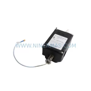
SKU: 31000-00-00-00-070-03-02
Bently Nevada 31000-00-00-00-070-03-02 Service-Ready Spare Part for Industrial Maintenance
Catalog Continuation
Alternative parts within TSI & Rotating Machinery Monitoring.
Stay inside the same system family when you need substitutes, adjacent modules, or a broader shortlist for procurement review.
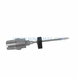
SKU: 21000-28-10-00-167-04-02
Bently Nevada 21000-28-10-00-167-04-02 Retrofit Proximity Probe
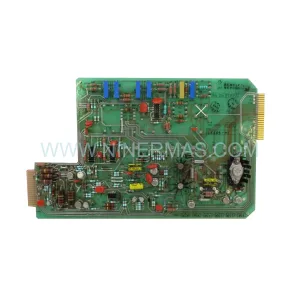
SKU: 330880-16-15-020-01-02
Bently Nevada 330880-16-15-020-01-02 Service-Ready Spare Part