Original Industrial Spare Part
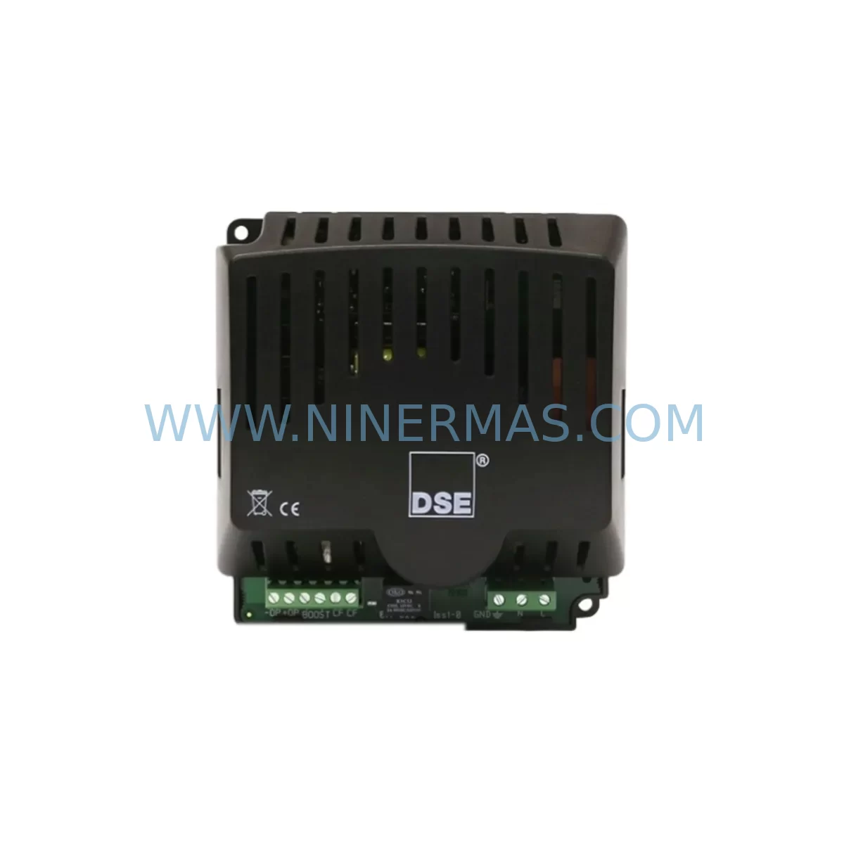
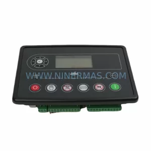
DSE DSE9130 MKII Retrofit-Compatible Controller for Legacy Systems
Verify the part, confirm the platform family, and move straight into quotation with the right commercial details.
RFQ Ready
- SKUDSE9130 MKII
- CategoryPLC & Industrial Automation Modules
- BrandDeep Sea Electronics
- SupportAvailability, lead time, condition, and shipping coordination
How Buyers Usually Use This Page
- Confirm the exact part number and platform family before sending the quote request.
- Use direct email when quantity, condition, and destination are already defined internally.
- Switch to the broader brand or category archive when you need alternates nearby.
Series Navigation
Move through the most common platform families behind this part.
Product RFQ
Send this part directly for quotation.
Include quantity, required condition, destination country, and target delivery timing. Current reference: DSE DSE9130 MKII Retrofit-Compatible Controller for Legacy Systems with SKU DSE9130 MKII.
DSE DSE9130 MKII Retrofit-Compatible Controller for Legacy Systems
The Deep Sea Electronics DSE9130 MKII is a professional-grade automatic mains failure (AMF) and automatic transfer switch (ATS) controller engineered for seamless integration into existing generator control panels and legacy automation systems. As a direct retrofit replacement for the discontinued DSE9130 and broader DSE9000 series platform, this unit is purpose-built to minimize engineering rework, reduce panel downtime, and restore full generator management capability without requiring a complete control system overhaul.
Whether you are managing a critical power facility, upgrading an aging standby generator installation, or sourcing obsolete spare parts to extend the operational life of your existing infrastructure, the DSE9130 MKII delivers the compatibility, reliability, and technical depth that industrial and commercial engineers demand. With a 12-month warranty, pre-shipment functional testing, and verified stock availability, this controller is a trusted solution for retrofit projects across power generation, marine, telecoms, and data center applications.
Upgrade Compatibility Table
| Parameter | DSE9130 (Original) | DSE9130 MKII (Retrofit) |
|---|---|---|
| Supply Voltage | 8–35V DC | 8–35V DC (identical) |
| Panel Cutout | Standard DIN cutout | Same cutout — no panel modification required |
| Terminal Layout | Legacy screw terminal block | Compatible terminal mapping; verify wiring schedule before swap |
| Communication Ports | RS-232 / RS-485 | RS-232 / RS-485 + USB (expanded) |
| SCADA / Modbus | Modbus RTU | Modbus RTU + optional Ethernet via DSE855 Communications Interface |
| Configuration Tool | DSE Configuration Suite (legacy) | DSE Configuration Suite PC Software (current version) |
| Firmware Upload | Factory only | Field-upgradeable via USB |
| I/O Expansion | Limited onboard I/O | Compatible with DSE2130 I/O Expansion Module |
| Installation Space | Standard panel depth | Confirm rear clearance for USB and comms connectors |
| Commissioning | Manual parameter entry | PC-based configuration file upload recommended |
| Warranty | N/A (discontinued) | 12 Months — NINERMAS Verified |
| Replacement Recommendation | Direct drop-in retrofit. Verify terminal schedule, load configuration file, confirm comms link before energizing. | |
Retrofit Planning for Existing Automation Systems
A successful DSE9130 MKII retrofit begins well before the unit arrives on site. Engineers replacing a failed or end-of-life DSE9130 in an existing generator control cabinet should start by documenting the full terminal wiring schedule from the original installation drawings. The DSE9130 MKII shares the same physical footprint and DC supply range, so panel cutout modification is not required — however, the rear connector layout for the USB port and expanded communications interface requires confirmation of rear panel clearance, particularly in compact or back-to-back cabinet configurations.
Power supply integrity is the first checkpoint. The DSE9130 MKII operates on an 8–35V DC supply, typically sourced from the generator battery. Before installation, verify that the existing battery charger module or DC power supply rail is delivering stable voltage within this range under both float and boost charge conditions. In installations where the original DSE9130 was powered from a shared DC bus alongside other modules — such as a DSE8610 MKII load sharing controller or a DSE5110 MKII AMF controller in a parallel generation system — confirm that the bus voltage remains within tolerance when all modules are energized simultaneously.
Terminal block wiring should be transferred systematically, one circuit at a time, using the original wiring schedule as the reference document. Pay particular attention to the configurable digital inputs and relay outputs, as the MKII firmware may assign default functions differently from the legacy unit. Use the DSE Configuration Suite PC Software to upload a pre-prepared configuration file that mirrors the original parameter set — this eliminates manual re-entry errors and significantly reduces commissioning time. If the original configuration file is unavailable, the parameters must be reconstructed from the original installation documentation or from a site survey of the existing system behavior.
For sites running SCADA or BMS integration via Modbus RTU over RS-485, verify that the slave address, baud rate, parity, and stop bit settings in the DSE9130 MKII match the polling configuration of the upstream SCADA system. In installations where Ethernet-based monitoring is required, the DSE855 Communications Interface module can be added to the control panel to provide TCP/IP connectivity without replacing the controller itself. This is particularly relevant for facilities migrating from serial-only SCADA architectures to modern IP-based monitoring platforms.
I/O expansion requirements should be assessed during the planning phase. If the original installation used a DSE2130 Remote I/O Expansion Module to extend digital inputs or relay outputs beyond the onboard capacity of the DSE9130, confirm that the MKII firmware version supports the same expansion module addressing scheme. In multi-generator installations, the DSE9130 MKII integrates with DSE8610 MKII load sharing and synchronizing modules via the DSENet communications bus — verify that the DSENet wiring, termination resistors, and module addressing are correctly configured before attempting parallel operation.
HMI and operator panel compatibility should also be reviewed. If the existing installation includes a remote annunciator panel or a dedicated DSE890 PC interface software connection, confirm that the MKII firmware version is supported by the current software release. In some legacy installations, the operator interface was provided by a third-party HMI connected via RS-232 — in these cases, verify that the HMI communication driver supports the DSE9130 MKII register map, as minor differences between MKII and original firmware versions may affect data point addressing.
Finally, confirm that all ancillary components in the control cabinet — including the engine interface harness, magnetic pickup speed sensor wiring, CT and VT measurement inputs, and any external protection relay interlocks — are correctly connected and verified before the first start attempt. A pre-commissioning checklist covering all of these points will reduce the risk of nuisance trips, failed starts, or protection relay misoperation during the initial energization sequence.
Downtime Control During System Migration
Minimizing generator downtime during a DSE9130 MKII retrofit requires a structured approach to pre-staging, configuration preparation, and on-site execution. The most effective strategy is to prepare and verify the replacement controller fully before taking the generator offline — this means uploading and validating the configuration file on the bench, confirming all parameter settings against the original documentation, and performing a functional test of the relay outputs and digital inputs using a test harness before the unit is installed in the panel.
Where the generator provides standby power to a critical load — such as a data center UPS bypass, a hospital essential services board, or a telecoms base station — coordinate the retrofit window with the facility operations team to ensure that an alternative power source or manual bypass arrangement is in place for the duration of the outage. In sites with parallel generator sets, it may be possible to transfer load to the remaining healthy units while the affected generator is taken offline for controller replacement, provided that the remaining capacity is sufficient to carry the full site load.
During the physical swap, label all terminal connections before disconnection and photograph the original wiring for reference. Transfer connections one circuit at a time, verifying each against the wiring schedule before proceeding to the next. Once all connections are made, perform a continuity check on all control wiring before applying DC supply power. Power up the controller in configuration mode first, verify that all parameter settings are correct, then perform a manual start test before returning the generator to automatic standby mode.
The original program logic — including start delay timers, transfer delay settings, protection relay thresholds, and alarm configurations — must be verified against the site-specific requirements before the generator is returned to service. Do not rely on default factory settings, as these are unlikely to match the original installation parameters. A signed commissioning record documenting all verified parameters, test results, and the identity of the commissioning engineer provides the audit trail required for compliance with generator maintenance standards and insurance requirements.
Retrofit Support FAQ
Q1: Is the DSE9130 MKII a direct replacement for the original DSE9130?
Yes. The DSE9130 MKII is designed as a form-fit-function replacement for the original DSE9130. The panel cutout dimensions and DC supply requirements are identical. Terminal wiring is compatible, but we recommend verifying the full wiring schedule against the MKII terminal assignment document before installation, as some configurable I/O assignments may differ from the original factory default configuration.
Q2: Can I upload my original DSE9130 configuration file to the MKII?
In most cases, yes. The DSE Configuration Suite PC Software supports configuration file migration between DSE9130 and DSE9130 MKII. However, we recommend reviewing the migrated file parameter by parameter before uploading to the replacement unit, as firmware version differences may affect the availability or behavior of certain configuration options. Contact our technical support team if you require assistance with configuration file migration.
Q3: What pre-shipment testing is performed on the DSE9130 MKII?
Every DSE9130 MKII unit supplied by NINERMAS undergoes a functional pre-shipment test covering DC supply input, digital input response, relay output operation, display functionality, and communications port verification. A test report is available on request. All units are supplied with a 12-month warranty covering manufacturing defects and functional failures under normal operating conditions.
Q4: What is the typical lead time and do you hold stock?
NINERMAS maintains verified stock of the DSE9130 MKII to support urgent retrofit and breakdown replacement requirements. Standard orders are dispatched within 1–3 business days. For large-quantity or project-specific requirements, contact our sales team at sale@ninermas.com or +0086 187 5021 5667 to confirm availability and arrange priority dispatch.
| Product Series | Legacy |
|---|---|
| Country of Origin | GB |
Catalog Continuation
More Deep Sea Electronics modules in the catalog.
Use the brand lane to compare nearby part numbers, platform-adjacent modules, and other inquiry-ready listings before sending your final RFQ.
Catalog Continuation
Alternative parts within PLC & Industrial Automation Modules.
Stay inside the same system family when you need substitutes, adjacent modules, or a broader shortlist for procurement review.
SKU: SCE906A2-002-01 SCE906A200201
Pacific Scientific SCE906A2-002-01 Retrofit Servo Amplifier
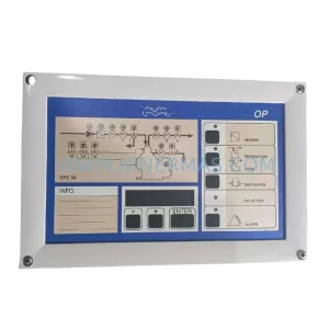
SKU: EPC500 3183062451
Alfa Laval EPC500 3183062451 Service-Ready Spare Part