Original Industrial Spare Part
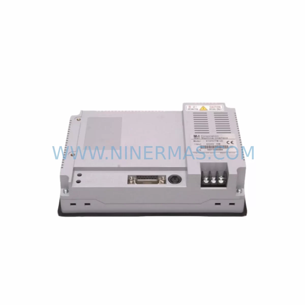
M2I XTOP07TW-UD Retrofit HMI Touch Panel for Legacy Systems
Verify the part, confirm the platform family, and move straight into quotation with the right commercial details.
RFQ Ready
- SKUXTOP07TW-UD
- CategoryPLC & Industrial Automation Modules
- BrandM2I
- SupportAvailability, lead time, condition, and shipping coordination
How Buyers Usually Use This Page
- Confirm the exact part number and platform family before sending the quote request.
- Use direct email when quantity, condition, and destination are already defined internally.
- Switch to the broader brand or category archive when you need alternates nearby.
Series Navigation
Move through the most common platform families behind this part.
Product RFQ
Send this part directly for quotation.
Include quantity, required condition, destination country, and target delivery timing. Current reference: M2I XTOP07TW-UD Retrofit HMI Touch Panel for Legacy Systems with SKU XTOP07TW-UD.
M2I XTOP07TW-UD Retrofit HMI Touch Panel for Legacy Systems
The M2I XTOP07TW-UD is a 7-inch TFT widescreen HMI touch panel engineered for seamless integration into existing automation architectures. Designed as a retrofit-compatible replacement for legacy XTOP series displays and equivalent third-party HMI units, this panel supports direct substitution in control cabinets where panel cutout dimensions, communication ports, and power supply ratings must remain unchanged. Whether you are modernizing a legacy production line, replacing a discontinued HMI in a running system, or restoring a control cabinet after an unplanned failure, the XTOP07TW-UD delivers the display performance and protocol compatibility required to maintain operational continuity without redesigning the control architecture.
The XTOP07TW-UD operates on a 24 VDC supply, making it directly compatible with standard DIN-rail mounted power supply modules already present in most industrial control cabinets. Its RS-232C, RS-422/485, and USB host/device ports allow it to communicate with a broad range of PLCs, motion controllers, and remote I/O systems from major manufacturers. The panel supports Ethernet connectivity for network-based SCADA integration and remote monitoring, enabling engineers to retain existing HMI-to-controller communication links without rewiring terminal blocks or replacing communication modules.
Upgrade Compatibility Table
| Parameter | XTOP07TW-UD Specification | Retrofit Notes |
|---|---|---|
| Display Size | 7-inch TFT Widescreen | Verify panel cutout dimensions before installation; standard XTOP series cutout compatible |
| Power Supply | 24 VDC (±10%) | Compatible with existing 24 VDC cabinet power rails; no additional PSU required |
| Serial Communication | RS-232C / RS-422 / RS-485 | Retain existing serial cable and terminal wiring; confirm baud rate and parity settings in project file |
| Ethernet | 10/100 Mbps (RJ-45) | Supports SCADA and remote access; configure IP address to match existing network segment |
| USB Ports | USB Host + USB Device | Use USB host for project upload/download; USB device for PC-based EzDesigner programming |
| PLC Compatibility | Multi-brand driver library | Supports LS Electric (formerly LSIS), Mitsubishi, Siemens, Omron, Delta, Schneider, and others via built-in drivers |
| Programming Software | EzDesigner (M2I) | Import existing XTOP project files; verify screen resolution mapping for widescreen format |
| Installation Depth | Confirm with datasheet | Measure available cabinet depth; ensure rear connector clearance before mounting |
| Operating Temperature | 0°C to 50°C | Confirm cabinet thermal management; add ventilation if replacing a unit in a sealed enclosure |
| Warranty | 12 Months | Covered from date of shipment; pre-shipment functional test included |
Retrofit Planning for Existing Automation Systems
A successful retrofit using the XTOP07TW-UD begins with a thorough audit of the existing control cabinet. Engineers should document the current HMI model, its panel cutout dimensions, power supply wiring, and all communication cable connections before removing the legacy unit. In most installations, the 24 VDC power terminals can be transferred directly to the XTOP07TW-UD without modification, provided the existing power supply module — such as a DIN-rail 24 VDC SMPS unit — delivers sufficient current capacity for the new panel’s rated consumption.
Communication wiring is typically the most critical step. If the legacy HMI was connected to a PLC via RS-485 multi-drop, the existing terminal block wiring and cable shielding can be reused. Engineers must confirm the RS-485 address, baud rate, data bits, stop bits, and parity settings in the EzDesigner project file to match the PLC driver configuration. For systems using Ethernet-based communication — for example, connecting to a Mitsubishi Q-series or iQ-R series CPU module via SLMP or MC Protocol — the IP address and subnet mask must be reconfigured to match the plant network segment.
Where the legacy system included a remote I/O rack connected to the HMI for local data acquisition, engineers should verify that the XTOP07TW-UD’s driver library includes the appropriate protocol for the remote I/O module in use. In many LS Electric-based systems, the HMI communicates directly with XGK or XGB series CPU modules via Cnet or Ethernet, while analog and digital I/O signals are handled by XGF or XGQ I/O modules mounted on the same base rack. The XTOP07TW-UD supports these communication paths natively, allowing the existing I/O architecture to remain intact.
For control cabinets that also house a motion controller or servo drive system, the HMI project may include axis status screens, alarm pages, and parameter setting screens linked to the drive’s register map. When migrating from an older XTOP model, engineers should review the tag address mapping in the EzDesigner project to confirm that all device addresses remain valid for the connected controller. If the legacy project was built for a 4:3 aspect ratio display, screen layouts will require adjustment for the XTOP07TW-UD’s widescreen format — a process that can be completed within EzDesigner’s screen editor without rebuilding the tag database.
In systems where a programming cable or USB-to-serial adapter was previously used to download projects to the HMI, the XTOP07TW-UD’s USB device port allows direct connection to a PC running EzDesigner, eliminating the need for legacy serial programming cables. A USB flash drive connected to the USB host port can also be used for field project updates without a laptop, which is particularly useful in remote installations or during scheduled maintenance windows where minimizing downtime is a priority.
Installations that include a signal isolator between the HMI serial port and the PLC communication port should retain the isolator to protect against ground loop interference, particularly in environments with variable-frequency drives or high-current motor starters in the same cabinet. The XTOP07TW-UD’s RS-485 port is compatible with standard 2-wire and 4-wire isolator configurations.
Downtime Control During System Migration
Minimizing unplanned downtime during an HMI replacement is a primary concern for maintenance engineers and plant managers. The XTOP07TW-UD retrofit process is designed to support a structured, low-risk migration that protects the existing PLC program logic and preserves field control continuity throughout the changeover.
The recommended approach is to prepare and validate the new HMI project file on a bench setup before the scheduled maintenance window. Using EzDesigner, engineers can import the existing project, adjust screen layouts for the widescreen format, verify all tag addresses, and simulate communication with the target PLC using the software’s offline simulation mode. This pre-validation step eliminates the most common sources of commissioning delay — incorrect baud rate settings, mismatched device addresses, and missing alarm page links — before the panel is installed in the cabinet.
During the physical changeover, the PLC program running in the CPU module — whether an LS Electric XGK, XGB, or equivalent controller — does not need to be modified. The PLC continues to execute its ladder or structured text program independently of the HMI. This means the field I/O, output relays, and safety interlocks remain active during the HMI swap, provided the PLC is not placed in stop mode. Engineers should confirm with the site safety officer whether a controlled stop is required before removing the legacy HMI from the cabinet.
Once the XTOP07TW-UD is physically mounted and wired, the pre-validated project file can be downloaded via USB in under five minutes. After download, the panel performs a self-test and establishes communication with the PLC automatically. Engineers should verify all alarm pages, setpoint entry screens, and trend displays are functioning correctly before returning the system to production. The entire changeover — from panel removal to verified communication — can typically be completed within a single two-hour maintenance window when the project file has been prepared in advance.
For systems where a backup of the original HMI project file is unavailable, M2I’s EzDesigner software includes an upload function that can retrieve the project from the legacy panel’s internal memory before removal, provided the panel is still powered and functional. This backup step is strongly recommended before any HMI replacement to preserve the original screen logic, tag database, and alarm configuration.
Retrofit Support FAQ
Q1: Is the XTOP07TW-UD a direct drop-in replacement for my existing XTOP series HMI?
The XTOP07TW-UD is designed as a retrofit-compatible replacement within the M2I XTOP product family. Panel cutout dimensions, power supply voltage, and communication port types are consistent with the XTOP series standard. Engineers should verify the specific cutout size and connector positions against the datasheet for the legacy model being replaced before ordering. EzDesigner project files from earlier XTOP models can be imported and adapted for the XTOP07TW-UD’s widescreen display format.
Q2: Which PLCs and controllers is the XTOP07TW-UD compatible with?
The XTOP07TW-UD supports a broad multi-brand driver library covering LS Electric (XGK, XGB, XEC series), Mitsubishi (FX, Q, iQ-R series), Siemens (S7-200, S7-300, S7-1200), Omron (CP, CJ, CS series), Delta, Schneider (Modicon), and others. Communication is supported via RS-232C, RS-422/485, Ethernet (TCP/IP), and USB. Confirm the specific driver version and protocol settings in EzDesigner before commissioning.
Q3: What pre-shipment testing is performed on the XTOP07TW-UD?
Each unit undergoes a functional pre-shipment test covering display operation, touch input calibration, communication port continuity, and power supply acceptance. Units that pass all test criteria are shipped with a 12-month warranty from the date of shipment. A test record is available upon request for quality documentation purposes.
Q4: What is the lead time and stock availability for the XTOP07TW-UD?
Stock availability is maintained to support urgent replacement requirements. Standard lead time for in-stock units is 3–7 business days for international shipment. For large-quantity orders or scheduled maintenance programs requiring multiple units, contact our sales team at sale@ninermas.com to confirm current inventory levels and arrange priority dispatch. All units are covered by a 12-month warranty and ship with pre-shipment test documentation.
| Product Series | Legacy |
|---|
Catalog Continuation
Alternative parts within PLC & Industrial Automation Modules.
Stay inside the same system family when you need substitutes, adjacent modules, or a broader shortlist for procurement review.
SKU: 16-167627-00 8122 410 05002, 4022.470.78191 8122 410 55702 16-273491-00
Novellus 16-167627-00 Service-Ready Industrial Spare Part
SKU: 2305451-C DT2000 0626 P2, OLE36-10632-02
Advanced Energy 2305451-C Service-Ready Industrial Spare Part