Original Industrial Spare Part
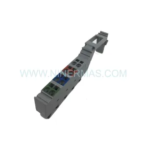
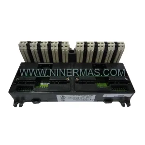
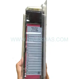
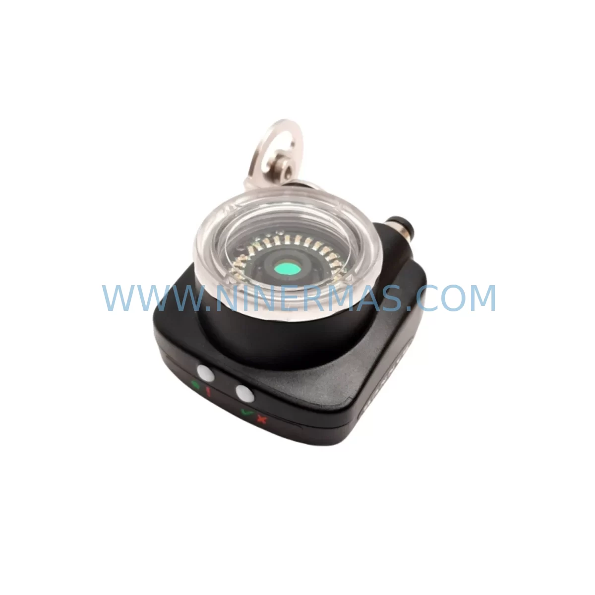
Banner IVUTGPR04 Service-Ready Spare Part for Industrial Maintenance
Verify the part, confirm the platform family, and move straight into quotation with the right commercial details.
RFQ Ready
- SKUIVUTGPR04 TSBC-ACRTC 881-620160 281-501049-C 208-501049-7
- CategoryPLC & Industrial Automation Modules
- BrandBanner Engineering
- SupportAvailability, lead time, condition, and shipping coordination
How Buyers Usually Use This Page
- Confirm the exact part number and platform family before sending the quote request.
- Use direct email when quantity, condition, and destination are already defined internally.
- Switch to the broader brand or category archive when you need alternates nearby.
Series Navigation
Move through the most common platform families behind this part.
Product RFQ
Send this part directly for quotation.
Include quantity, required condition, destination country, and target delivery timing. Current reference: Banner IVUTGPR04 Service-Ready Spare Part for Industrial Maintenance with SKU IVUTGPR04 TSBC-ACRTC 881-620160 281-501049-C 208-501049-7.
Banner IVUTGPR04 Service-Ready Spare Part for Industrial Maintenance
The Banner IVUTGPR04 is a precision image sensor from Banner Engineering’s iVu TG (Trigger Gate) series, widely deployed in automated inspection, part presence detection, and machine vision applications across automotive assembly, electronics manufacturing, food and beverage packaging, and general industrial automation. When this sensor fails or degrades, production lines halt — and every minute of unplanned downtime translates directly into lost output and recovery costs. Maintaining a service-ready IVUTGPR04 spare in your critical parts inventory is one of the most effective strategies for minimizing mean time to repair (MTTR) and restoring normal operations within a 4–6 hour window.
NINERMAS supplies the Banner IVUTGPR04 as an original, service-ready spare part, pre-shipment tested and backed by a 12-month warranty. Each unit is verified for electrical integrity and functional performance before dispatch, ensuring that the replacement you receive is ready for immediate installation without additional bench testing delays on-site.
Spare Maintenance Table
| Parameter | Specification |
|---|---|
| Part Number | IVUTGPR04 |
| Brand | Banner Engineering |
| Series | iVu TG (Trigger Gate) Vision Sensor Series |
| Product Type | Industrial Image Sensor / Vision Sensor |
| Compatible SKUs | IVUTGPR04, TSBC-ACRTC, 881-620160, 281-501049-C, 208-501049-7 |
| Supply Voltage | 10–30 VDC |
| Output Type | PNP / NPN discrete outputs; RS-232 serial communication |
| Communication Interface | RS-232, Ethernet (model-dependent) |
| Operating Temperature | 0°C to +50°C |
| Protection Rating | IP67 |
| Mounting | Standard M18 / bracket mount; compatible with iVu series mounting hardware |
| Application Environment | Automotive, Electronics, Food & Beverage, General Industrial Automation |
| Maintenance Recommendation | Inspect lens and housing quarterly; verify output signal integrity during annual PM |
| Origin | United States |
| Warranty | 12 Months — NINERMAS Pre-Shipment Tested |
Maintenance Planning for Continuous Operation
Replacing the IVUTGPR04 in a live production environment requires more than a direct sensor swap. Maintenance engineers and procurement teams should treat this replacement as an opportunity to audit the surrounding electrical and control infrastructure to prevent secondary failures and reduce the risk of repeat downtime events.
Begin by inspecting the sensor’s power supply circuit. The Banner PSW-24-1 or equivalent 24 VDC regulated power supply feeding the iVu TG sensor should be checked for output voltage stability and ripple. A degraded power supply is a common root cause of intermittent sensor faults that are often misdiagnosed as sensor failure. Alongside the power supply, verify the condition of the Banner MQDC-406 or MQDC-415 quick-disconnect cordsets connecting the sensor to the control panel — damaged or corroded connectors are a frequent source of signal loss and false triggers.
Within the control cabinet, inspect the I/O module receiving the IVUTGPR04’s discrete outputs. If the system uses a Siemens S7-300 or S7-1200 PLC, verify the corresponding digital input module (such as the SM 321 or SM 1221) for channel integrity. For Allen-Bradley ControlLogix or CompactLogix platforms, check the 1756-IB16 or 1769-IQ16 input cards for any burned or high-resistance input channels that may have been stressed by the sensor fault event.
Communication integrity should also be confirmed. If the IVUTGPR04 is connected via RS-232 to a Banner iVu series remote display or to a host PLC serial module, inspect the Banner IVUDT-DISPLAY remote display unit and the associated serial cable for continuity. For Ethernet-connected variants, verify switch port status and cable integrity at the patch panel.
Relay outputs downstream of the sensor — particularly those driving reject actuators, alarm indicators, or interlock circuits — should be tested for contact resistance and proper switching. Phoenix Contact or Weidmuller relay modules in the same cabinet are common candidates for inspection during an iVu TG sensor replacement event.
Terminal blocks and DIN rail wiring associated with the sensor’s I/O loop should be torque-checked and inspected for insulation damage. Fuse holders protecting the sensor power circuit — typically 1A or 2A slow-blow fuses — should be replaced as a precautionary measure if the sensor failure was accompanied by any power anomaly.
For facilities running Banner PresencePLUS P4 series vision sensors or Banner QS30 photoelectric sensors in adjacent inspection stations, this maintenance window is an ideal time to perform a cross-check of those units’ output signals and lens cleanliness, as contamination and vibration-induced misalignment often affect multiple sensors in the same production zone simultaneously.
Site Replacement Workflow
A structured on-site replacement workflow for the IVUTGPR04 minimizes downtime and ensures system compatibility is maintained throughout the transition.
Step 1 — Isolation and Lockout/Tagout: De-energize the sensor circuit following your facility’s LOTO procedure. Confirm zero energy state at the sensor connector before disconnecting.
Step 2 — Configuration Backup: If the existing IVUTGPR04 is still partially functional, use the Banner iVu series configuration software (iVu Plus BCR or iVu TG Configurator) to export the current inspection program, including all teach points, trigger settings, and output logic. Store the backup on a local engineering workstation and a network share.
Step 3 — Physical Replacement: Remove the failed unit, noting the mounting orientation and cable routing. Install the service-ready IVUTGPR04 spare in the same position. Reconnect the MQDC cordset and verify connector locking engagement.
Step 4 — Configuration Restore: Load the backed-up inspection program onto the replacement sensor. Verify all teach points, pass/fail thresholds, and output assignments match the original configuration.
Step 5 — Functional Verification: Run a controlled test cycle with known-good and known-bad reference parts to confirm the sensor is detecting correctly. Verify discrete output signals at the PLC I/O module and confirm the HMI status display reflects correct sensor state.
Step 6 — Documentation: Record the replacement in your maintenance management system (CMMS), including the failed unit’s serial number, replacement date, and any observations about the failure mode. Update your spare parts inventory to trigger a replenishment order for the consumed IVUTGPR04 unit.
Spare Parts Support FAQ
Q1: Is the IVUTGPR04 supplied by NINERMAS an original Banner Engineering part?
Yes. NINERMAS supplies original Banner IVUTGPR04 units sourced through established industrial distribution channels. Each unit undergoes pre-shipment functional testing and is covered by a 12-month warranty from the date of delivery.
Q2: How do I confirm compatibility between the IVUTGPR04 and my existing iVu TG installation?
Compatibility is confirmed by matching the part number IVUTGPR04 against your existing sensor label and the associated cross-reference SKUs: TSBC-ACRTC, 881-620160, 281-501049-C, and 208-501049-7. If your installation uses a specific firmware version or custom configuration, contact NINERMAS before ordering to confirm interchangeability.
Q3: What is the typical lead time, and does NINERMAS maintain reserved stock?
NINERMAS maintains reserved inventory of high-demand Banner iVu TG series components to support urgent replacement requirements. Standard lead time for in-stock units is 3–7 business days for international shipments. For facilities with recurring maintenance schedules, NINERMAS offers long-term supply agreements with reserved stock allocation to eliminate lead time risk during planned annual shutdowns.
Q4: What does the 12-month warranty cover, and what is the claims process?
The 12-month warranty covers manufacturing defects and functional failures under normal operating conditions. It does not cover damage resulting from incorrect installation, overvoltage events, or physical impact. To initiate a warranty claim, contact NINERMAS with the original invoice number, a description of the failure symptom, and photographic evidence of the unit condition. Replacement or repair will be arranged within 5 business days of claim approval.
| Product Series | Other series |
|---|
Catalog Continuation
More Banner Engineering modules in the catalog.
Use the brand lane to compare nearby part numbers, platform-adjacent modules, and other inquiry-ready listings before sending your final RFQ.
SKU: SLPR14-270NP8 SGMAS-C2AGA-SU12 CDN500R-64 0090-05656
Banner SLPR14-270NP8 Retrofit Light Curtain for Legacy Systems
Catalog Continuation
Alternative parts within PLC & Industrial Automation Modules.
Stay inside the same system family when you need substitutes, adjacent modules, or a broader shortlist for procurement review.
SKU: 6FC5357-0BB12-0AE0
Siemens 6FC5357-0BB12-0AE0 Service-Ready Industrial Spare Part
SKU: 3BSE011790R1(PXHK401)
ABB 3BSE011790R1 PXHK401 Retrofit-Ready Communication Module