Original Industrial Spare Part
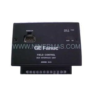
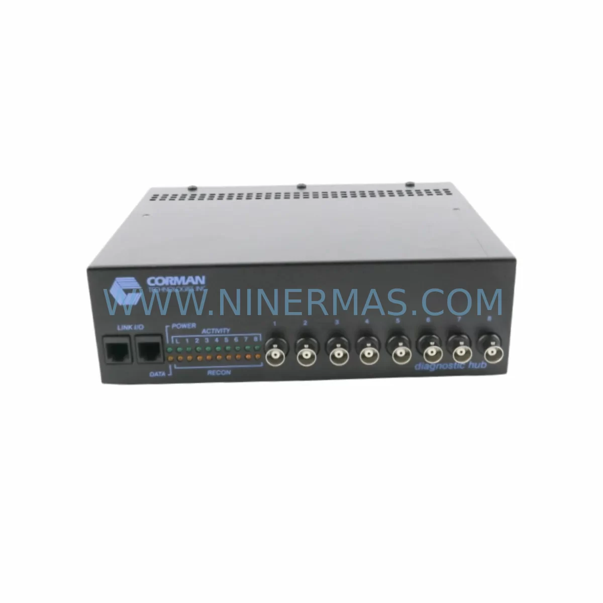
Corman CT-N806-839-443215-401 Retrofit Diagnostic Module
Verify the part, confirm the platform family, and move straight into quotation with the right commercial details.
RFQ Ready
- SKUCT-N806 839-443215-401 SI 716-082039-289
- CategoryPLC & Industrial Automation Modules
- BrandCorman Technologies
- SupportAvailability, lead time, condition, and shipping coordination
How Buyers Usually Use This Page
- Confirm the exact part number and platform family before sending the quote request.
- Use direct email when quantity, condition, and destination are already defined internally.
- Switch to the broader brand or category archive when you need alternates nearby.
Series Navigation
Move through the most common platform families behind this part.
Product RFQ
Send this part directly for quotation.
Include quantity, required condition, destination country, and target delivery timing. Current reference: Corman CT-N806-839-443215-401 Retrofit Diagnostic Module with SKU CT-N806 839-443215-401 SI 716-082039-289.
Corman CT-N806-839-443215-401 Retrofit Diagnostic Module: Retrofit-Compatible Upgrade for Legacy Industrial Control Systems
The Corman Technologies CT-N806-839-443215-401 (cross-reference: SI-716-082039-289) is a retrofit-compatible diagnostic module engineered to serve as a direct replacement for end-of-life and discontinued diagnostic units in legacy industrial control architectures. As automation systems age and OEM support windows close, maintenance engineers and system integrators face mounting pressure to source reliable, pre-tested spare parts that can be installed without rewriting control logic or redesigning cabinet layouts. This module addresses that challenge directly, offering a validated drop-in solution for facilities running aging distributed control systems, legacy PLC backplanes, and first-generation process automation platforms.
Whether your facility operates a legacy rack-mounted control system with aging I/O infrastructure or a distributed automation network that predates modern fieldbus standards, the CT-N806-839-443215-401 is designed to restore diagnostic visibility and system integrity with minimal disruption to ongoing production. NINERMAS maintains ready inventory of this module with pre-shipment functional testing and a 12-month warranty on every unit shipped.
Upgrade Compatibility Table
| Parameter | Details |
|---|---|
| Primary Part Number | CT-N806-839-443215-401 |
| Cross-Reference / Alternate SKU | SI-716-082039-289 |
| Module Function | Industrial Diagnostic Module — system fault detection, status monitoring, and diagnostic data relay |
| Installation Compatibility | Rack-mount backplane; verify slot pitch, guide rail dimensions, and connector keying against existing chassis before installation |
| Communication Interface | Confirm fieldbus or backplane communication protocol (RS-485, Profibus, or proprietary backplane bus) matches host controller configuration |
| Power Supply Requirement | Verify DC bus voltage (typically 24 VDC) and current draw against existing rack power supply capacity before hot-swap or cold-swap installation |
| Terminal / Connector Type | Check front-panel terminal block pitch and wiring gauge compatibility; re-use existing field wiring where possible to reduce commissioning time |
| Module Address Configuration | Set DIP switches or rotary address selectors to match the original module address; confirm address map in the host PLC or DCS configuration file |
| Program / Logic Compatibility | No PLC program rewrite required for direct replacement; validate diagnostic data tags and HMI screen bindings post-installation |
| Replacement Recommendation | Direct replacement for discontinued CT-N806 series diagnostic units; suitable for legacy system life extension and spare parts inventory replenishment |
| Pre-Shipment Testing | 100% functional test performed on every unit prior to dispatch |
| Warranty | 12-Month Warranty — covers manufacturing defects and functional failures under normal operating conditions |
Retrofit Planning for Existing Automation Systems
Successful integration of the CT-N806-839-443215-401 into an existing control system begins well before the module arrives on site. Retrofit planning for legacy diagnostic modules requires a structured review of the entire control cabinet ecosystem — not just the slot being replaced.
Start with a power audit. The existing rack power supply module must have sufficient headroom to support the replacement diagnostic unit. In many aging systems, the original power supply is already operating near its rated output, particularly in cabinets where additional I/O expansion modules or communication modules have been added over the years. Confirm the available DC bus capacity and, if necessary, plan for a parallel power supply upgrade before the diagnostic module swap.
Next, review the backplane and chassis. The CT-N806-839-443215-401 is designed for rack-mount installation, and the host backplane must present compatible slot connectors and bus architecture. In systems where the original backplane has been in service for a decade or more, inspect the backplane connector pins for oxidation or mechanical wear. If the backplane itself is approaching end-of-life, it is advisable to source a replacement backplane unit from the same control platform series at the same time, avoiding a second maintenance window in the near future.
Terminal wiring and field connections are the next checkpoint. The front-panel terminal block on the CT-N806-839-443215-401 should accept the existing field wiring gauge and terminal pitch. Document the original wiring layout with photographs before disconnecting any conductors. In retrofit projects involving older systems, field wiring insulation may be brittle, and disturbing connections unnecessarily increases the risk of incidental faults. Where signal isolation is required between the diagnostic module and field sensors, a signal isolator or signal conditioner module should be inserted in the signal path to protect both the new module and the host controller from transient interference.
Communication link verification is critical in systems that rely on fieldbus protocols for diagnostic data transmission. Whether the host system uses a legacy serial communication module, a Profibus DP interface, or a proprietary backplane communication bus, the replacement diagnostic module must be configured to match the original node address and baud rate settings. In systems where a communication gateway module bridges the legacy fieldbus to a modern Ethernet-based supervisory network, confirm that the gateway’s device table still maps correctly to the new module’s node address after replacement.
HMI screen validation is often overlooked in diagnostic module replacements. If the facility’s operator interface — whether a standalone HMI panel or a SCADA workstation — displays diagnostic status data sourced from this module, verify that all screen tags and alarm bindings remain functional after the swap. In some legacy HMI configurations, diagnostic data is polled by tag name rather than by module address, which simplifies post-replacement validation. In others, the HMI configuration file may need a minor update to reflect the new module’s register map if any differences exist between the original and replacement units.
For systems undergoing broader modernization — such as migrating from a legacy PLC platform to a current-generation controller — the CT-N806-839-443215-401 can serve as a bridging component, maintaining diagnostic coverage during the transition period while the new control platform is commissioned in parallel. In such projects, a programming cable and laptop running the legacy programming software are essential tools for reading out and archiving the original program logic before any hardware changes are made.
Downtime Control During System Migration
Minimizing unplanned downtime is the primary operational concern in any diagnostic module replacement or control system retrofit. The CT-N806-839-443215-401 supports a structured, low-risk replacement methodology that preserves original program logic and maintains field control continuity throughout the migration process.
The recommended approach is a cold-swap replacement during a scheduled maintenance window. Before powering down the rack, archive the current PLC program and all relevant configuration files to a secure backup location. Photograph the existing wiring, record the module address settings, and note the current diagnostic status indicators. Power down the rack in the correct sequence — field power first, then control power — to avoid transient faults on the backplane bus.
After installing the CT-N806-839-443215-401 and restoring wiring connections, power up the system in reverse sequence and observe the module’s status indicators during initialization. Confirm that the host controller recognizes the module at the expected backplane address and that diagnostic data is being transmitted correctly to the supervisory system. Run a full I/O check and alarm test before returning the system to automatic operation.
For facilities where even a brief planned shutdown is operationally sensitive, NINERMAS can support pre-delivery configuration and bench testing of the replacement module against customer-supplied specifications, further reducing on-site commissioning time and the risk of unexpected issues during the maintenance window.
Retrofit Support FAQ
Q: Is the CT-N806-839-443215-401 a direct replacement for the original CT-N806 series diagnostic module?
A: Yes. The CT-N806-839-443215-401 is sourced and tested as a direct replacement for the original CT-N806 series. The cross-reference number SI-716-082039-289 confirms compatibility with systems that reference either part number. Always verify backplane connector type, module address range, and communication protocol settings against your system documentation before installation.
Q: What pre-shipment testing is performed, and does the module carry a warranty?
A: Every CT-N806-839-443215-401 unit shipped by NINERMAS undergoes 100% functional testing prior to dispatch. Each unit is covered by a 12-month warranty against manufacturing defects and functional failures under normal operating conditions. Warranty claims are supported directly by NINERMAS with fast replacement dispatch to minimize production impact.
Q: Do I need to modify my PLC program or HMI configuration after replacing the diagnostic module?
A: In most direct replacement scenarios, no PLC program modification is required. However, it is strongly recommended to validate all HMI diagnostic screen tags, alarm bindings, and communication link status after installation. If the replacement module’s register map differs from the original in any way, minor HMI tag updates may be needed. NINERMAS technical support can assist with compatibility verification prior to shipment.
Q: Is stock available for immediate shipment, and can I order multiple units for spare parts inventory?
A: NINERMAS maintains ready inventory of the CT-N806-839-443215-401 for immediate dispatch. Multiple units can be ordered to support spare parts inventory programs, long-term service agreements, or planned retrofit projects. Contact our team to discuss volume availability, lead times, and reserved inventory arrangements for critical automation assets.
| Product Series | Other series |
|---|
Catalog Continuation
Alternative parts within PLC & Industrial Automation Modules.
Stay inside the same system family when you need substitutes, adjacent modules, or a broader shortlist for procurement review.
SKU: 6FC5370-8AA20-0AA0
SIEMENS 6FC5370-8AA20-0AA0 Retrofit-Compatible CNC Memory
SKU: 6SL3020-2TE21-0AA4
Siemens 6SL3020-2TE21-0AA4 Service-Ready Spare Part
SKU: DX100DX200 jZRCR-YPP01-1 JZRCR-YPP21-1 SRDA-SDB95A01A-E 10Y-06A DC-24V
Yaskawa JZRCR-YPP01-1 Retrofit-Compatible Pendant for Legacy Systems