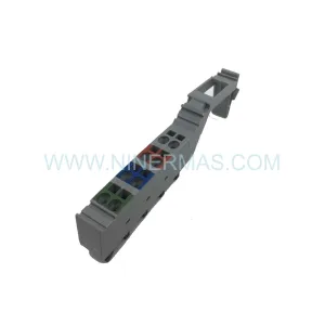
Original Industrial Spare Part
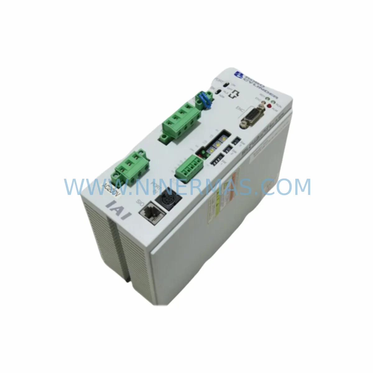
IAI RCS-C-SM-1-100-1-P Service-Ready Spare Part
Verify the part, confirm the platform family, and move straight into quotation with the right commercial details.
RFQ Ready
- SKURCS-C-SM-1-100-1-P
- CategoryPLC & Industrial Automation Modules
- BrandIAI
- SupportAvailability, lead time, condition, and shipping coordination
How Buyers Usually Use This Page
- Confirm the exact part number and platform family before sending the quote request.
- Use direct email when quantity, condition, and destination are already defined internally.
- Switch to the broader brand or category archive when you need alternates nearby.
Series Navigation
Move through the most common platform families behind this part.
Product RFQ
Send this part directly for quotation.
Include quantity, required condition, destination country, and target delivery timing. Current reference: IAI RCS-C-SM-1-100-1-P Service-Ready Spare Part with SKU RCS-C-SM-1-100-1-P.
IAI RCS-C-SM-1-100-1-P Service-Ready Spare Part for Industrial Maintenance
The IAI RCS-C-SM-1-100-1-P is a dedicated controller unit within IAI’s RCS (Robo Cylinder Series) actuator ecosystem, designed to drive and position single-axis electric actuators in precision automation environments. When a production line halts due to a failed actuator controller, every minute of downtime translates directly into lost output and escalating recovery costs. Sourcing a verified, service-ready replacement for the RCS-C-SM-1-100-1-P is the fastest path to restoring motion control integrity and resuming normal operations.
At NINERMAS, we stock the RCS-C-SM-1-100-1-P as a long-term spare parts commitment — not a one-time listing. Each unit is inspected, function-tested, and shipped with a 12-month warranty, giving maintenance engineers and procurement teams the confidence to plan both emergency replacements and scheduled annual overhauls around a reliable supply chain.
Spare Maintenance Table
| Parameter | Specification / Detail |
|---|---|
| Part Number | RCS-C-SM-1-100-1-P |
| Brand | IAI (Intelligent Actuator Inc.) |
| Series | RCS — Robo Cylinder Series |
| Product Type | Single-Axis Actuator Controller |
| Control Mode | Position / Speed / Push-force control via pulse train or serial command |
| Compatible Actuators | IAI RCS series single-axis rod and slider type electric actuators |
| Input Power Supply | Single-phase AC 100–115 V / 200–230 V (model-dependent); confirm nameplate before installation |
| Motor Output Rating | 100 W (as indicated by suffix “100” in SKU) |
| Communication Interface | Serial (RS-232C / RS-485 depending on variant); compatible with IAI PCON/ACON teaching pendant |
| I/O Interface | Digital I/O for PLC interlock; position complete, alarm, and enable signals |
| Mounting | DIN rail or panel mount; standard RCS-C footprint |
| Operating Temperature | 0 °C to +40 °C; humidity 10–90% RH non-condensing |
| Protection Class | IP20 (control cabinet installation required) |
| Origin | Japan |
| Condition | Original-spec spare; inspected and function-tested |
| Warranty | 12 Months — NINERMAS Standard Spare Parts Warranty |
| Lead Time | Typically in stock; confirm availability at sale@ninermas.com |
Maintenance Planning for Continuous Operation
Replacing the RCS-C-SM-1-100-1-P in isolation rarely resolves the root cause of an actuator system failure. Experienced maintenance engineers treat a controller replacement as the trigger for a broader cabinet and circuit inspection. Before returning the axis to automatic mode, the following associated components should be verified or replaced as part of the same maintenance window:
Power supply integrity is the first checkpoint. The RCS-C-SM-1-100-1-P relies on a stable 24 VDC logic supply — typically sourced from a dedicated DIN-rail power supply such as an IAI PS-241 or equivalent MEAN WELL or Phoenix Contact unit. A degraded power supply that caused the original controller failure will damage the replacement unit within weeks if left unchecked. Measure output voltage under load and replace if ripple or voltage drop exceeds specification.
Motor cable and encoder cable condition must be assessed before reconnecting the actuator. Damaged shielding on the motor cable introduces EMI that corrupts encoder feedback, triggering position deviation alarms on the RCS-C-SM-1-100-1-P. Inspect the full cable run from the controller to the actuator body, paying particular attention to bend-radius violations at cable carriers and drag chains.
PLC I/O module health is equally critical. The digital output cards driving the RCS-C-SM-1-100-1-P enable and command signals — often Mitsubishi MELSEC QX or Omron CJ1W-OD series modules — should be scanned for blown output channels. A shorted I/O channel can hold the controller in a fault state even after a successful hardware replacement.
Terminal block and wiring harness inspection should cover the 24 VDC logic wiring, the I/O connector, and the RS-232C/RS-485 communication cable. Loose or corroded terminals on Phoenix Contact or Weidmüller terminal blocks are a common source of intermittent faults that mimic controller failure. Re-torque all terminals and replace any discoloured or heat-damaged wiring.
Communication chain verification is required if the RCS-C-SM-1-100-1-P is networked to a host PLC or HMI via serial link. Check the RS-485 termination resistor, verify baud rate and station address settings match the original configuration, and confirm that the IAI teaching pendant or PC software (e.g., IAI PC Software) can establish communication before handing the axis back to production.
Regenerative resistor and braking circuit should be inspected on vertical or high-inertia axes. If the application involves frequent deceleration of a heavy load, the regenerative resistor connected to the RCS-C-SM-1-100-1-P may have degraded. A failed regenerative circuit causes overvoltage faults and can destroy the replacement controller’s internal drive stage.
HMI and operator panel — if the axis status is displayed on a Proface GP or Keyence VT series HMI, verify that the screen tag addresses and communication settings still match after the controller replacement, particularly if the station address was reset to factory default during the swap.
Safety relay and interlock circuit review is mandatory before re-enabling the axis. Confirm that the emergency stop relay (e.g., Pilz PNOZ or Omron G9SA series) correctly de-energises the RCS-C-SM-1-100-1-P servo-on signal and that the safety circuit has not been bypassed during the maintenance intervention.
Documenting all findings and replacement actions in the equipment maintenance log ensures that the next scheduled inspection — typically at 6- or 12-month intervals — can be completed efficiently and that procurement can plan buffer stock for the highest-risk components identified during this event.
Site Replacement Workflow
Step 1 — Isolate and de-energise. Switch off the main circuit breaker for the control cabinet. Lock out / tag out (LOTO) per site safety procedure. Confirm zero voltage at the RCS-C-SM-1-100-1-P power terminals with a calibrated multimeter.
Step 2 — Record existing configuration. Before disconnecting any cables, photograph the wiring, note the DIP switch and rotary switch settings on the original RCS-C-SM-1-100-1-P, and export or transcribe the position data table from the controller memory using the IAI teaching pendant or PC software. This data must be re-entered into the replacement unit.
Step 3 — Remove the failed unit. Disconnect the motor cable, encoder cable, I/O connector, communication cable, and power terminals in sequence. Slide the controller off the DIN rail or remove the panel-mount screws. Retain all hardware.
Step 4 — Install the replacement RCS-C-SM-1-100-1-P. Mount the new unit, reconnect all cables in reverse order, and verify that DIP switch and rotary switch settings match the recorded configuration. Torque all terminal screws to specification.
Step 5 — Restore power and verify communication. Re-energise the cabinet and confirm that the IAI teaching pendant or PC software establishes communication with the replacement controller. Re-enter the position data table and verify all programmed positions against the machine’s mechanical reference marks.
Step 6 — Functional test in manual mode. Jog the actuator through its full stroke in manual mode, checking for smooth motion, correct position feedback, and absence of alarm codes. Verify push-force operation if applicable.
Step 7 — Return to automatic mode. Enable the PLC interlock, release the LOTO, and run the machine through a supervised automatic cycle before returning it to full production speed. Record the replacement date, unit serial number, and test results in the maintenance log.
This structured workflow minimises the risk of repeat failures, reduces total downtime from fault to recovery, and ensures that the replacement RCS-C-SM-1-100-1-P is operating within its design envelope from the first production cycle.
Spare Parts Support FAQ
Q1: Is the RCS-C-SM-1-100-1-P compatible with all IAI RCS series actuators?
The RCS-C-SM-1-100-1-P is designed for IAI RCS series single-axis actuators with a 100 W motor rating. Compatibility depends on the actuator’s motor type, encoder specification, and stroke. Always cross-reference the actuator’s nameplate data and the original controller’s model code before ordering. NINERMAS technical support can assist with compatibility verification — contact sale@ninermas.com with your actuator model number.
Q2: How is the unit tested before shipment?
Every RCS-C-SM-1-100-1-P dispatched by NINERMAS undergoes a pre-shipment functional inspection covering power-on self-test, communication interface check, and I/O signal verification. Units that do not pass inspection are not shipped. A test report summary is available on request.
Q3: What does the 12-month warranty cover?
The NINERMAS 12-month warranty covers manufacturing defects and functional failures under normal operating conditions from the date of shipment. It does not cover damage caused by incorrect installation, overvoltage, or use outside the rated specification. Warranty claims are processed via sale@ninermas.com with proof of purchase and a fault description.
Q4: Can NINERMAS support long-term or blanket-order procurement for the RCS-C-SM-1-100-1-P?
Yes. NINERMAS operates a long-term spare parts programme for critical industrial components, including the IAI RCS series. Customers with multi-site maintenance programmes or annual MRO budgets can negotiate stock commitments, priority allocation, and extended lead-time guarantees. Contact our sales team at sale@ninermas.com or +0086 187 5021 5667 to discuss your requirements.
| Product Series | Other series |
|---|
Catalog Continuation
More IAI modules in the catalog.
Use the brand lane to compare nearby part numbers, platform-adjacent modules, and other inquiry-ready listings before sending your final RFQ.
SKU: DS-S-C1-L DSSC1LDS
IAI DS-S-C1-L Safety-Reliable Output Module for Control
Catalog Continuation
Alternative parts within PLC & Industrial Automation Modules.
Stay inside the same system family when you need substitutes, adjacent modules, or a broader shortlist for procurement review.
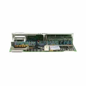
SKU: 6FC5357-0BB12-0AE0
Siemens 6FC5357-0BB12-0AE0 Service-Ready Industrial Spare Part
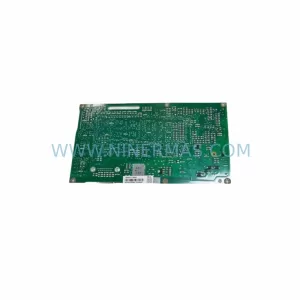
SKU: 3BSE011790R1(PXHK401)
ABB 3BSE011790R1 PXHK401 Retrofit-Ready Communication Module