Original Industrial Spare Part
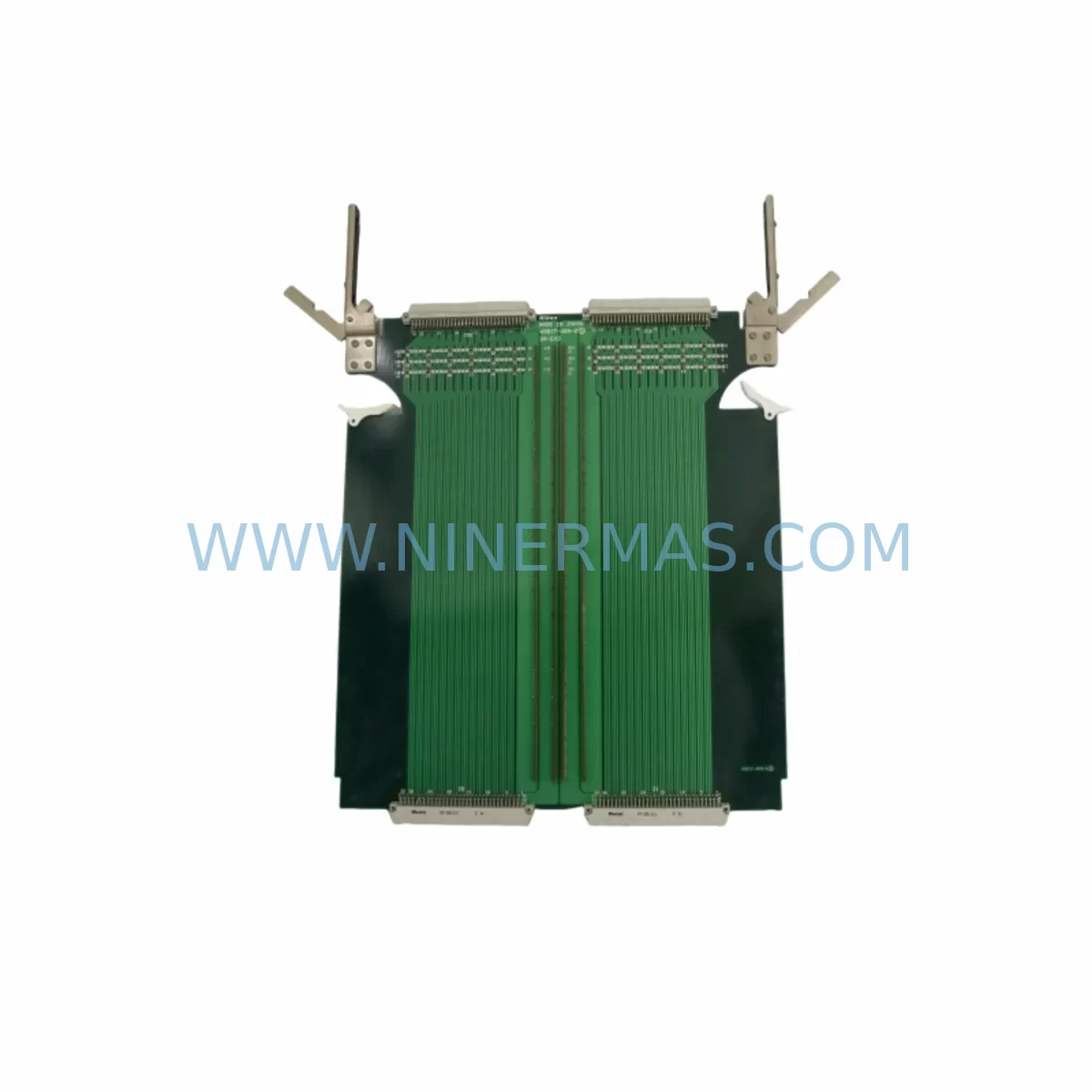
Nikon 4S017-489-2 Service-Ready Spare for Industrial Maintenance
Verify the part, confirm the platform family, and move straight into quotation with the right commercial details.
RFQ Ready
- SKUSR-EX3 4S017-489-2 0021-12555 LBC-GX 400-0332-000B
- CategoryPLC & Industrial Automation Modules
- BrandNikon
- SupportAvailability, lead time, condition, and shipping coordination
How Buyers Usually Use This Page
- Confirm the exact part number and platform family before sending the quote request.
- Use direct email when quantity, condition, and destination are already defined internally.
- Switch to the broader brand or category archive when you need alternates nearby.
Series Navigation
Move through the most common platform families behind this part.
Product RFQ
Send this part directly for quotation.
Include quantity, required condition, destination country, and target delivery timing. Current reference: Nikon 4S017-489-2 Service-Ready Spare for Industrial Maintenance with SKU SR-EX3 4S017-489-2 0021-12555 LBC-GX 400-0332-000B.
Nikon 4S017-489-2 Service-Ready Spare for Industrial Maintenance
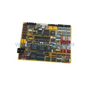
The Nikon 4S017-489-2 PCB Assembly is a critical spare part for SR-EX3 series semiconductor lithography and precision inspection systems. When this board fails, the entire production line halts — costing manufacturers thousands of dollars per hour in unplanned downtime. Sourcing a verified, service-ready replacement from a reliable supplier is the fastest path to restoring full system operation. NINERMAS maintains ready stock of the 4S017-489-2 to support emergency replacement, scheduled overhaul, and long-term spare parts inventory programs for maintenance engineers and procurement teams worldwide.
Each unit is sourced from original production channels, subjected to pre-shipment functional testing, and backed by a 12-month warranty. Whether you are managing a single critical asset or building a multi-site spare parts library, the 4S017-489-2 is available for immediate dispatch with full traceability documentation.
Spare Maintenance Table
| Parameter | Details |
|---|---|
| Part Number | 4S017-489-2 |
| Cross-Reference SKUs | 0021-12555 / LBC-GX-400-0332-000B |
| Series Compatibility | Nikon SR-EX3 Series |
| Component Type | PCB Assembly (Printed Circuit Board Assembly) |
| Application | Semiconductor lithography, precision optical inspection, industrial automation control |
| Operating Voltage | Refer to SR-EX3 system electrical specification (typically 24 VDC logic rail) |
| Installation Interface | Backplane slot / direct board replacement per SR-EX3 service manual |
| Environmental Rating | Cleanroom-compatible; controlled temperature and humidity environment |
| Pre-Shipment Testing | Functional verification performed on each unit prior to dispatch |
| Warranty | 12 Months from date of shipment |
| Lead Time | In-stock units ship within 1–3 business days; reserved stock available on request |
| Origin | Japan (OEM) |
Maintenance Planning for Continuous Operation
Replacing the 4S017-489-2 PCB Assembly is rarely an isolated task. Experienced maintenance engineers know that a board failure in the SR-EX3 control architecture often signals stress across adjacent subsystems. A thorough site inspection should accompany any PCB swap to prevent repeat failures and reduce the risk of secondary downtime events.
Begin by inspecting the LBC-GX-400 power supply module that feeds the logic board rail. Voltage ripple or marginal regulation is a common root cause of PCB degradation in long-running SR-EX3 installations. Simultaneously, verify the condition of the 0021-12555 interface board, which handles signal routing between the PCB assembly and downstream I/O subsystems. A degraded interface board can cause intermittent faults that are difficult to isolate without replacing both components together.
Check the SR-EX3 backplane connector for oxidation, bent pins, or thermal discoloration. Backplane integrity is essential for stable communication between the PCB assembly and the system’s motion control and vision processing modules. If the system uses Nikon 4S017-490 series signal conditioning boards, inspect these for capacitor bulge or trace corrosion — they share the same environmental exposure as the 4S017-489-2 and often reach end-of-life simultaneously.
For systems with extended service histories, audit the relay output modules and terminal block assemblies in the control cabinet. Relay contacts in high-cycle applications accumulate wear that can cause false triggering or signal loss after a PCB replacement restores normal system sensitivity. Replace any relay showing contact resistance above specification.
Communication integrity should also be verified. Inspect RS-232 and RS-422 communication cables connecting the PCB assembly to the host controller or HMI panel. Cable shielding degradation is a frequent source of noise injection that accelerates PCB failure. If the installation includes signal isolators on analog I/O channels, test isolation resistance and replace any unit showing leakage.
Finally, review the fuse block and circuit protection assembly in the control cabinet. A blown or weakened fuse on the 24 VDC logic rail may have contributed to the original PCB failure. Replacing fuses as a matter of course during a PCB swap is low-cost insurance against repeat events. Document all findings in the maintenance log to support future spare parts planning and warranty claims.
Site Replacement Workflow
Step 1 — Preparation: Obtain the 4S017-489-2 replacement unit and confirm the part number and revision marking against the installed board. Gather the SR-EX3 service manual and ensure ESD protection equipment is available. Power down the system following the OEM lockout/tagout procedure.
Step 2 — Removal: Disconnect all cable harnesses from the PCB assembly in sequence, labeling each connector if not already marked. Release the board retention mechanism and extract the 4S017-489-2 from the backplane slot. Inspect the slot for debris or damage before installing the replacement.
Step 3 — Installation: Seat the replacement 4S017-489-2 firmly into the backplane slot, ensuring all edge connectors are fully engaged. Reconnect cable harnesses in reverse order. Verify that no cables are pinched or under tension.
Step 4 — Verification: Restore power and observe system startup diagnostics. Confirm that all I/O channels, communication links, and motion control feedback signals are operating within specification. Run a short functional test cycle before returning the system to production.
Step 5 — Documentation: Record the replacement date, part number, serial number, and test results in the maintenance management system. Retain the failed board for root cause analysis if required under your quality management process. Initiate a spare parts replenishment order to restore your on-hand inventory buffer.
This workflow is designed to minimize total downtime from fault detection to production resumption. With a service-ready 4S017-489-2 in stock, most sites can complete the replacement within a single maintenance window, avoiding the extended lead times associated with emergency procurement from OEM channels.
Spare Parts Support FAQ
Q1: Is the 4S017-489-2 compatible with all SR-EX3 system variants?
The 4S017-489-2 PCB Assembly is designed for the Nikon SR-EX3 series. Compatibility should be confirmed against your specific system revision and service manual. NINERMAS technical support can assist with cross-referencing your installed revision against available stock. Cross-reference part numbers 0021-12555 and LBC-GX-400-0332-000B are associated with this assembly and can be used to verify fitment.
Q2: What testing is performed before shipment?
Every 4S017-489-2 unit undergoes pre-shipment functional verification at NINERMAS before dispatch. Testing covers power-on initialization, I/O channel continuity, and communication interface integrity. A test report is available upon request. Units that do not pass verification are not shipped. This process ensures that replacement boards perform correctly from the first power-on at your site.
Q3: What is the recommended spare parts inventory strategy for SR-EX3 systems?
For critical production assets, NINERMAS recommends maintaining a minimum of one 4S017-489-2 on-site as a hot spare, with a second unit in regional warehouse stock. For multi-system installations, a pooled spare strategy with reserved inventory agreements provides the best balance of cost and availability. NINERMAS offers long-term supply agreements and reserved stock programs to support planned maintenance cycles and annual overhaul schedules.
Q4: What does the 12-month warranty cover?
The 12-month warranty covers manufacturing defects and functional failures under normal operating conditions from the date of shipment. Warranty claims are supported by NINERMAS with replacement or repair at no additional cost. The warranty does not cover damage resulting from incorrect installation, overvoltage events, or use outside the specified environmental parameters. All warranty claims should be submitted to sale@ninermas.com with the original order reference and a description of the failure mode.
| Product Series | Other series |
|---|
Catalog Continuation
More Nikon modules in the catalog.
Use the brand lane to compare nearby part numbers, platform-adjacent modules, and other inquiry-ready listings before sending your final RFQ.
SKU: 4S018-713-1 NSR-S306C
NIKON 4S018-713-1 NSR-S306C Safety-Reliable Control Board
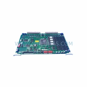
SKU: 4S015-173 NK-C304-40 4S015-205 C304-BT-31
NIKON 4S015-173 NK-C304-40 Retrofit Controller for NK-C304
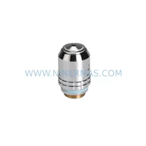
SKU: 150X/0.90 WD 0.29 200/300 RIGHT W/ 0040-76219 SPACER 0040-76221 200/300 LEFT W/ 0040-76219 SPACER 0040-76220
Nikon CF Plan Apo 150X/0.90 Service-Ready Industrial Spare Part
Catalog Continuation
Alternative parts within PLC & Industrial Automation Modules.
Stay inside the same system family when you need substitutes, adjacent modules, or a broader shortlist for procurement review.