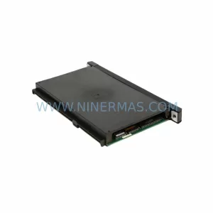
Original Industrial Spare Part
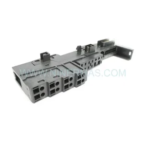
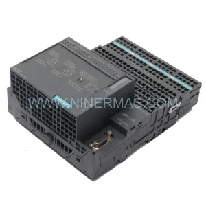
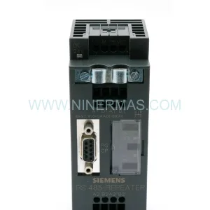
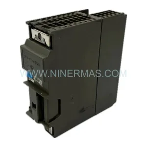
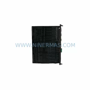
Bosch BM-DP12 1070075887-202 Retrofit-Compatible PROFIBUS DP Module
Verify the part, confirm the platform family, and move straight into quotation with the right commercial details.
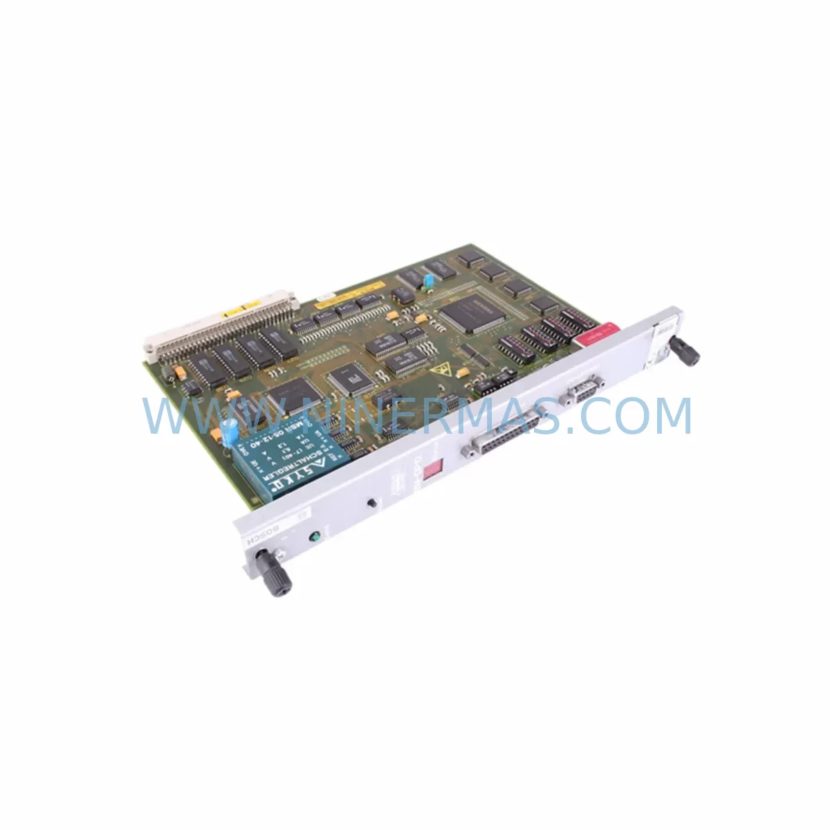
RFQ Ready
- SKUBM-DP12 1070075887-202
- CategoryPLC & Industrial Automation Modules
- BrandBosch
- SupportAvailability, lead time, condition, and shipping coordination
How Buyers Usually Use This Page
- Confirm the exact part number and platform family before sending the quote request.
- Use direct email when quantity, condition, and destination are already defined internally.
- Switch to the broader brand or category archive when you need alternates nearby.
Series Navigation
Move through the most common platform families behind this part.
Product RFQ
Send this part directly for quotation.
Include quantity, required condition, destination country, and target delivery timing. Current reference: Bosch BM-DP12 1070075887-202 Retrofit-Compatible PROFIBUS DP Module with SKU BM-DP12 1070075887-202.
Bosch BM-DP12 1070075887-202 Retrofit-Compatible PROFIBUS DP Module for Legacy System Modernization
The Bosch BM-DP12 (Part No. 1070075887-202) is a ruggedized PROFIBUS DP communication expansion module engineered for integration into Bosch CNC control systems, motion controllers, and distributed I/O architectures. As legacy Bosch automation platforms approach end-of-life, the BM-DP12 serves as a critical retrofit component enabling engineers to extend the operational lifespan of existing control cabinets without full system replacement. This module supports PROFIBUS DP protocol at up to 12 Mbit/s, making it directly compatible with legacy fieldbus networks still operating in discrete manufacturing, machine tool, and process automation environments.
NINERMAS maintains verified stock of the BM-DP12 1070075887-202 with pre-shipment functional testing, full traceability documentation, and a 12-month warranty covering defects in materials and workmanship. Each unit is inspected against Bosch OEM specifications before dispatch, ensuring drop-in compatibility with existing backplane slots and rack configurations.
Upgrade Compatibility Table
| Parameter | BM-DP12 1070075887-202 | Retrofit Notes |
|---|---|---|
| Communication Protocol | PROFIBUS DP (EN 50170) | Compatible with existing DP master/slave networks; no protocol bridge required |
| Transmission Rate | Up to 12 Mbit/s | Auto-baud detection; matches legacy network speed settings |
| Backplane Interface | Bosch BM-series rack slot | Verify rack generation (BM-V / BM-E series); confirm slot pitch and connector type before installation |
| Power Supply Requirement | 24 VDC via backplane | Confirm existing PSU capacity; add Bosch BM-PS24 or equivalent if total rail load is marginal |
| Installation Form Factor | Single-slot plug-in module | No additional mounting hardware required; confirm available slot position in rack |
| Node Address Configuration | DIP switch / software-configurable | Set PROFIBUS node address before insertion; document existing address map to avoid conflicts |
| GSD File Compatibility | Standard Bosch GSD file | Import GSD into STEP 7, TIA Portal, or Bosch IndraWorks for automatic parameter assignment |
| Operating Temperature | 0°C to +55°C (ruggedized) | Suitable for harsh cabinet environments; verify ambient temperature in retrofit enclosure |
| Replacement Scope | Direct OEM replacement | Replaces failed or end-of-life BM-DP12 units; no firmware modification required in most cases |
| Warranty | 12 Months | Covers manufacturing defects; pre-shipment functional test certificate included |
Retrofit Planning for Existing Automation Systems
Integrating the BM-DP12 1070075887-202 into a legacy control architecture requires a structured pre-installation assessment to minimize risk and ensure communication continuity. Before removing the failed or obsolete module, engineers should document the full rack layout, including the positions of adjacent modules such as the Bosch BM-AI8 analog input module, BM-DO16 digital output module, and any installed BM-CI communication interface cards. These neighboring modules share the backplane data bus, and their address assignments must remain undisturbed during the swap.
Power budget verification is a mandatory first step. The existing Bosch BM-PS24 power supply module must have sufficient headroom to support the BM-DP12’s backplane current draw alongside all other installed modules. If the rack is operating near its rated capacity, a supplementary power supply or load redistribution across a secondary rack may be required before the retrofit proceeds.
For systems where the BM-DP12 interfaces with a Bosch Rexroth IndraControl L or IndraControl V controller, the PROFIBUS DP master configuration stored in the controller’s project file must be reviewed. The GSD file for the BM-DP12 should be re-imported into the engineering tool — whether Bosch IndraWorks DS, Siemens STEP 7, or TIA Portal — to confirm that all I/O byte assignments, diagnostic addresses, and cyclic data lengths match the original configuration. Any mismatch in the DP telegram structure will cause the master to report a configuration fault at startup.
Terminal wiring on the PROFIBUS cable connector (DB9 or M12, depending on the cabinet design) must be verified against the original wiring diagram. Pin 3 (RxD/TxD-P), Pin 8 (RxD/TxD-N), and Pin 6 (VP +5V) are the critical signals; incorrect polarity will prevent the slave from joining the DP network. If the existing cable uses a PROFIBUS termination resistor plug at the segment end, confirm it remains in place after the module swap to maintain signal integrity across the bus.
In systems that also include Bosch Rexroth HMI panels (such as the VDP 16.2 or BTV series), the HMI project may contain symbolic variable links tied to the DP slave address of the BM-DP12. If the node address is changed during the retrofit — even temporarily — HMI communication alarms will trigger. It is best practice to maintain the original node address throughout the replacement process and only modify it if a documented address conflict exists.
Where the control system also incorporates Bosch Rexroth servo drives (such as the IndraDrive C or IndraDrive M series) connected via PROFIBUS DP, the drive parameters related to fieldbus communication (P-0-4077, P-0-4078) should be backed up before any rack work begins. A Bosch programming cable or USB-to-serial adapter with IndraWorks access is required for this backup procedure. This ensures that drive configuration can be restored rapidly if a communication fault occurs during commissioning of the new module.
For installations where the BM-DP12 is part of a larger I/O expansion strategy, engineers may also need to coordinate with Bosch BM-DI32 digital input modules and BM-AO4 analog output modules sharing the same rack. Confirming that the total I/O byte count does not exceed the DP master’s configured maximum is essential before bringing the network back online.
Downtime Control During System Migration
Minimizing production downtime during a BM-DP12 module replacement requires advance preparation and a disciplined commissioning sequence. The recommended approach is to perform all pre-work — GSD file verification, address documentation, power budget calculation, and wiring diagram review — during a scheduled maintenance window or shift changeover, so that the physical swap itself can be completed within a single planned outage.
Before powering down the rack, export a full backup of the PLC or CNC program from the controller. For Bosch IndraControl platforms, this includes the IEC 61131-3 program project, the PROFIBUS DP configuration, and any motion program libraries. Store the backup on an offline medium independent of the control cabinet. This protects the original program logic in the event that the controller requires a cold restart after the module replacement.
During the physical swap, handle the BM-DP12 by its front panel only and avoid touching the backplane connector pins. Insert the replacement module firmly until the locking lever engages. After power-up, monitor the module’s diagnostic LEDs: a steady green BF (Bus Fault) LED indicates successful DP network integration, while a flashing red LED signals a configuration mismatch that must be resolved in the engineering tool before production can resume.
If the system cannot tolerate a cold restart, consider using a PROFIBUS DP repeater to isolate the affected segment during the swap, allowing the remainder of the DP network to continue operating. This approach is particularly valuable in multi-drop networks where other slaves — such as variable frequency drives, remote I/O stations, or weighing terminals — must remain online during the maintenance activity.
Once the BM-DP12 is confirmed online and all DP slaves are reporting correctly, perform a controlled test cycle of the affected machine or process line before releasing it to production. Document the commissioning result, including the date, technician name, firmware version observed, and any parameter changes made. This record supports future maintenance planning and warranty claim processing if required.
Retrofit Support FAQ
Q1: Is the BM-DP12 1070075887-202 a direct replacement for the original Bosch part, or are there hardware revisions I need to verify?
The 1070075887-202 suffix identifies a specific hardware revision of the BM-DP12. In most cases, this revision is backward compatible with earlier BM-DP12 variants installed in the same rack generation. However, if your existing system uses a very early BM-series rack (pre-2000 manufacture), confirm the backplane connector pinout against the Bosch hardware manual before installation. NINERMAS can provide the relevant datasheet upon request prior to order.
Q2: What commissioning steps are required after installing the replacement module?
After physical installation, power up the rack and observe the BM-DP12 diagnostic LEDs. If the DP master reports a configuration fault, re-download the PROFIBUS DP configuration from your engineering tool (IndraWorks, STEP 7, or TIA Portal). Verify that the GSD file version matches the installed module revision. In most straightforward replacements where the node address and GSD file are unchanged, the module will join the DP network automatically within one bus cycle after power-up.
Q3: Does NINERMAS perform pre-shipment testing on the BM-DP12, and what does the 12-month warranty cover?
Yes. Every BM-DP12 unit shipped by NINERMAS undergoes functional power-on testing and PROFIBUS communication verification before dispatch. The 12-month warranty covers manufacturing defects and functional failures under normal operating conditions. It does not cover damage resulting from incorrect installation, overvoltage, or environmental conditions outside the module’s rated specification. A test certificate is included with each shipment.
Q4: Can NINERMAS support long-term supply of the BM-DP12 for ongoing maintenance programs?
Yes. NINERMAS operates a long-term spare parts program for discontinued and end-of-life Bosch industrial automation components. Customers with ongoing maintenance requirements for legacy Bosch BM-series systems can arrange blanket purchase orders or scheduled delivery programs to ensure continuous availability of the BM-DP12 and related modules. Contact our sales team to discuss inventory commitment and lead time terms.
| Product Series | Other series |
|---|
Catalog Continuation
More Bosch modules in the catalog.
Use the brand lane to compare nearby part numbers, platform-adjacent modules, and other inquiry-ready listings before sending your final RFQ.
SKU: TDM1.2-50-300-W1
Bosch TDM1.2-50-300-W1 Safety-Reliable DC Drive for Critical Control
SKU: D-64711 1070068007-102
BOSCH D-64711 1070068007-102 Service-Ready Spare Part for Industrial Maintenance
Catalog Continuation
Alternative parts within PLC & Industrial Automation Modules.
Stay inside the same system family when you need substitutes, adjacent modules, or a broader shortlist for procurement review.