Original Industrial Spare Part
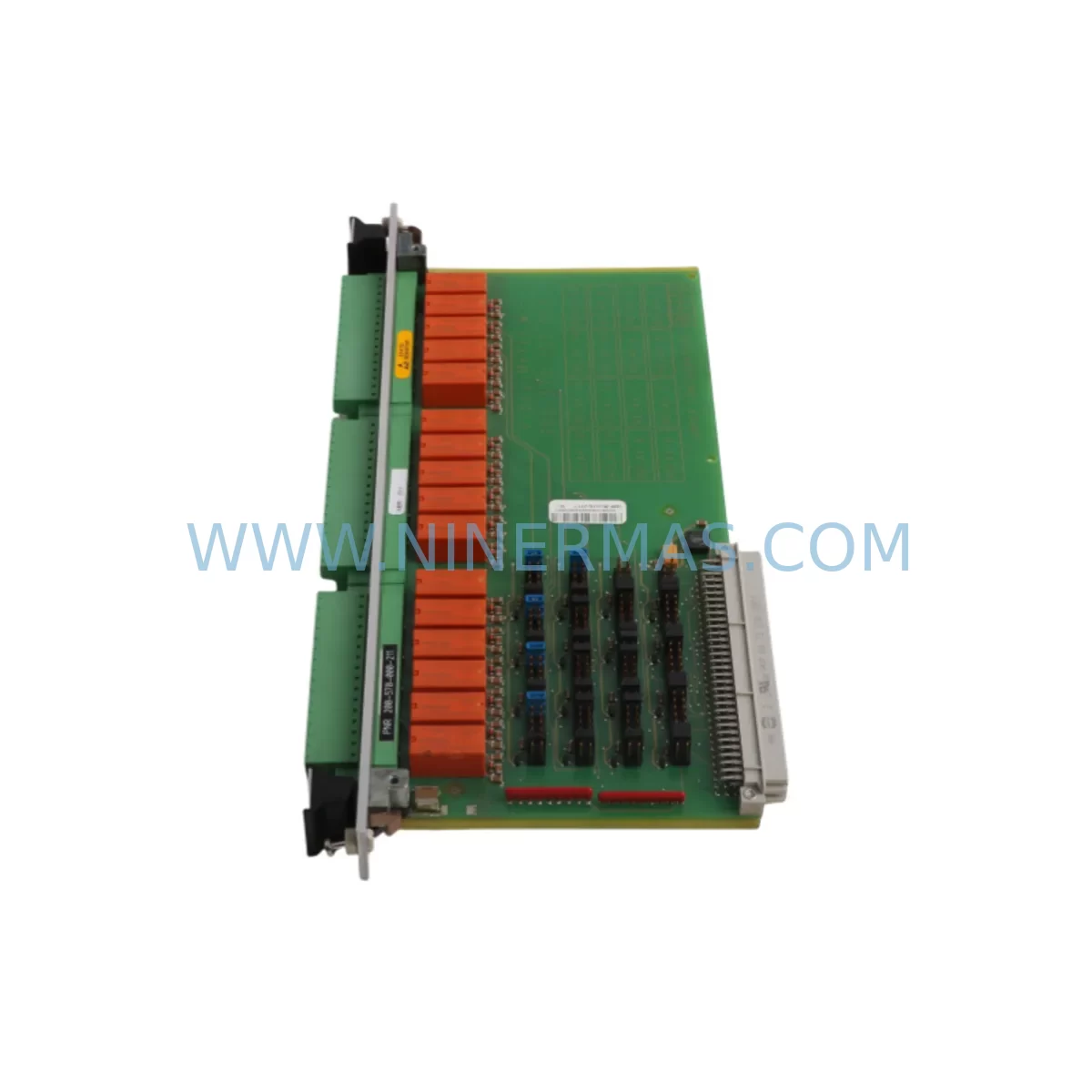
VIBRO-METER VM600 RLC16 200-570-000-211 Spare Part
Verify the part, confirm the platform family, and move straight into quotation with the right commercial details.
RFQ Ready
- SKUVM600 RLC16 200-570-000-211
- CategoryTSI & Rotating Machinery Monitoring
- BrandVibro-Meter
- SupportAvailability, lead time, condition, and shipping coordination
How Buyers Usually Use This Page
- Confirm the exact part number and platform family before sending the quote request.
- Use direct email when quantity, condition, and destination are already defined internally.
- Switch to the broader brand or category archive when you need alternates nearby.
Series Navigation
Move through the most common platform families behind this part.
Product RFQ
Send this part directly for quotation.
Include quantity, required condition, destination country, and target delivery timing. Current reference: VIBRO-METER VM600 RLC16 200-570-000-211 Spare Part with SKU VM600 RLC16 200-570-000-211.
VIBRO-METER VM600 RLC16 200-570-000-211 Spare Part: Relay Output Module for Industrial Maintenance & Downtime Recovery
The VIBRO-METER VM600 RLC16 200-570-000-211 is a ruggedized 16-channel relay output module engineered for the VM600 machinery protection and condition monitoring rack system. Designed for continuous operation in harsh industrial environments — including rotating machinery protection, turbine monitoring, compressor surveillance, and critical process plant applications — this relay module serves as the final output stage that drives alarm annunciators, shutdown logic, and DCS/PLC interlock circuits. When this module fails or degrades, the entire protection chain is compromised, making rapid spare part availability a non-negotiable element of any maintenance strategy.
At NINERMAS, every VM600 RLC16 200-570-000-211 unit is sourced as an original VIBRO-METER component, pre-shipment tested under functional load conditions, and dispatched with full documentation. Our 12-month warranty covers both parts and verified performance, giving maintenance engineers and procurement teams the confidence to stock this module as a critical spare without lifecycle risk.
Spare Maintenance Table
| Parameter | Specification / Detail |
|---|---|
| Part Number / SKU | 200-570-000-211 |
| Model | VM600 RLC16 |
| Brand | VIBRO-METER (Meggitt) |
| Series | VM600 Machinery Protection System |
| Module Type | 16-Channel Relay Output Module |
| Output Channels | 16 independent relay outputs |
| Relay Contact Rating | Typically 30 VDC / 1 A (SPDT, per VM600 series standard) |
| Backplane Compatibility | VM600 rack backplane (6U Eurocard format) |
| Communication Interface | Backplane bus — compatible with VM600 rack controller |
| Operating Temperature | 0 °C to +60 °C (standard industrial range) |
| Application Environment | Turbine halls, compressor stations, process plants, offshore platforms |
| Mounting | VM600 19-inch rack chassis slot insertion |
| Origin | Switzerland (VIBRO-METER / Meggitt SA) |
| Condition | Original spare — pre-shipment functional tested |
| Warranty | 12 Months — parts and verified performance |
| Lead Time | In-stock: 3–7 business days; ex-stock programs available |
| Certifications | CE marked; compliant with IEC 61511 / SIL-capable system architecture |
Maintenance Planning for Continuous Operation
The VM600 RLC16 200-570-000-211 sits at the output boundary of the VM600 protection rack. When planning a replacement or scheduled overhaul, maintenance engineers should treat this module as part of a broader relay output and protection circuit inspection. A relay output failure rarely occurs in isolation — associated components in the same rack and interlock loop must be evaluated concurrently to prevent repeat failures and ensure the protection system is fully restored.
During a VM600 rack inspection triggered by RLC16 degradation, the following components should be checked or staged as co-spares:
- VM600 AMC8 (200-580-000-xxx) — Analog Monitoring Card: The AMC8 processes vibration and process signals upstream of the relay output. A degraded AMC8 can produce false relay trips or missed alarms — always verify AMC8 channel calibration when replacing the RLC16.
- VM600 MPC4 / MPC4e — Machine Protection Card: The MPC4 is the core processing module that drives relay logic. If relay outputs are erratic, the MPC4 firmware and hardware should be inspected alongside the RLC16.
- VM600 Rack Backplane (200-510-xxx): Relay module contact faults can originate from backplane connector wear. Inspect backplane pins and edge connectors during RLC16 replacement.
- VM600 Power Supply Module (200-500-000-xxx): The rack power supply feeds all modules including the RLC16. Voltage ripple or supply instability can cause relay chatter. Verify DC rail stability with a multimeter before commissioning the replacement module.
- Terminal Blocks and Field Wiring (relay output terminals): Inspect screw-clamp terminal blocks connected to the RLC16 output field wiring. Loose or corroded terminals are a common cause of intermittent relay contact faults that are misdiagnosed as module failure.
- External Relay Interposing Modules (e.g., Phoenix Contact or Weidmüller relay bases): Many installations use interposing relays between the VM600 RLC16 outputs and the final shutdown actuators. These should be tested for coil resistance and contact continuity during any RLC16 replacement event.
- Fuse Holders and Protection Fuses (relay output circuits): Blown fuses on relay output circuits are a frequent companion fault. Replace or verify all fuses in the relay output wiring harness.
- DCS/PLC Digital Input Cards (receiving relay signals): Confirm that the DCS or PLC digital input cards receiving VM600 relay signals are reading correctly after module replacement. A failed DI card can mask a successful RLC16 repair.
- VM600 Configuration Software (VMConfig / Rack Configuration File): After physical replacement, reload and verify the rack configuration file. Relay channel assignments, trip setpoints, and time delays must be confirmed against the as-built documentation before returning the system to service.
Stocking the RLC16 200-570-000-211 alongside the AMC8, MPC4, and a rack power supply module as a coordinated spare set is the recommended strategy for plants operating VM600 systems in critical service. This approach reduces mean time to repair (MTTR) from days to hours and eliminates the risk of extended downtime caused by sequential part failures.
Site Replacement Workflow
Step 1 — Isolation and Permit: Obtain a Permit to Work (PTW) and coordinate with the control room to bypass or inhibit the affected protection channels in the DCS/SIS before removing the RLC16 module. Never remove a live relay output module without confirmed bypass — doing so may trigger spurious shutdowns.
Step 2 — Module Extraction: Power down the VM600 rack slot (if hot-swap is not supported in your configuration) or follow the VIBRO-METER hot-insertion procedure. Extract the RLC16 by releasing the front panel ejector levers. Label and photograph the slot position and wiring before disconnection.
Step 3 — Visual and Contact Inspection: Inspect the extracted RLC16 for burnt relay contacts, discolored PCB areas, or damaged backplane connectors. Document findings for the maintenance record.
Step 4 — Replacement Module Installation: Insert the new VIBRO-METER VM600 RLC16 200-570-000-211 into the correct rack slot. Ensure the module is fully seated against the backplane. Reconnect field wiring terminals and verify torque on screw-clamp connections.
Step 5 — Configuration Verification: Using VMConfig or the applicable VM600 configuration tool, confirm that the replacement module has loaded the correct channel configuration, relay logic assignments, and trip setpoints. Compare against the as-built rack configuration file.
Step 6 — Functional Test: With the control room on standby, perform a relay output functional test — inject a simulated alarm condition and verify that each relay channel operates correctly. Confirm DCS/PLC digital input receipt of relay status signals.
Step 7 — Return to Service: Remove protection bypasses in the correct sequence per the plant’s SIS bypass management procedure. Update the maintenance management system (CMMS) with the replacement record, new module serial number, and next recommended inspection interval.
This structured replacement workflow minimizes downtime, maintains SIL integrity, and ensures full traceability — critical requirements for rotating machinery protection systems in oil & gas, power generation, and petrochemical facilities.
Spare Parts Support FAQ
Q1: Is the VM600 RLC16 200-570-000-211 compatible with all VM600 rack configurations?
The RLC16 200-570-000-211 is designed for the standard VM600 6U rack backplane. Compatibility depends on the rack chassis version and firmware revision of the MPC4/MPC4e controller. NINERMAS recommends providing your rack serial number and existing module part numbers when ordering to allow cross-reference verification before shipment. Our technical team can confirm slot compatibility and configuration requirements prior to dispatch.
Q2: What pre-shipment testing does NINERMAS perform on the RLC16 module?
Every VM600 RLC16 200-570-000-211 unit undergoes functional relay contact testing, backplane connector inspection, and power-on verification before dispatch. Test records are available upon request. Units that do not pass functional testing are not shipped. This process is part of our standard quality assurance protocol and is covered under the 12-month warranty.
Q3: How should the RLC16 be stored as a long-term spare?
Store the module in its original anti-static packaging in a climate-controlled environment: temperature 15–25 °C, relative humidity below 60%, away from direct sunlight and electromagnetic interference sources. Inspect the module annually for connector oxidation. For plants with extended maintenance cycles (3–5 years), NINERMAS offers long-term supply agreements with reserved stock and fixed pricing to eliminate procurement risk during critical overhaul windows.
Q4: What is covered under the 12-month warranty and what are the return terms?
The 12-month warranty covers manufacturing defects, relay contact failure under normal operating conditions, and verified functional performance as tested at dispatch. Warranty claims require the module to be returned in its original packaging with a fault description. Physical damage caused by incorrect installation, overvoltage, or field wiring errors is excluded. NINERMAS provides a replacement or full refund within the warranty period. Contact sale@ninermas.com to initiate a warranty claim.
| Product Series | Other series |
|---|
Catalog Continuation
More Vibro-Meter modules in the catalog.
Use the brand lane to compare nearby part numbers, platform-adjacent modules, and other inquiry-ready listings before sending your final RFQ.
SKU: 204-900-000-011
Vibro-meter 204-900-000-011 Safety-Reliable Vibration Monitor
SKU: 111-412-000-012
Vibro-Meter 111-412-000-012 Retrofit-Compatible Module for VM600
SKU: GSI127 244-127-000-017 A1-B02
Vibro-Meter GSI127 244-127-000-017 A1-B02 Service-Ready Spare Part
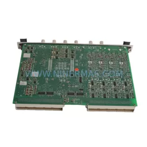
SKU: VM600 MPC4 200-510-041-021
VIBRO-METER VM600 MPC4 200-510-041-021 Safety Machinery Protection
Catalog Continuation
Alternative parts within TSI & Rotating Machinery Monitoring.
Stay inside the same system family when you need substitutes, adjacent modules, or a broader shortlist for procurement review.
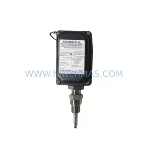
SKU: 330880-16-15-020-01-02
Bently Nevada 330880-16-15-020-01-02 Service-Ready Spare Part
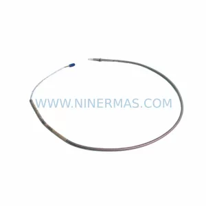
SKU: 330910-00-13-10-02-05
Bently Nevada 330910-00-13-10-02-05 Safety-Reliable Proximity Transducer
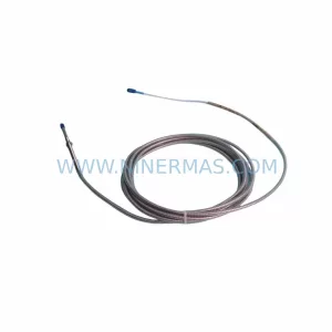
SKU: 330103-00-10-10-11-05
Bently Nevada 330103-00-10-10-11-05 Safety Proximity Transducer