Original Industrial Spare Part
Vibro-Meter 111-412-000-012 Retrofit-Compatible Module for VM600
Verify the part, confirm the platform family, and move straight into quotation with the right commercial details.
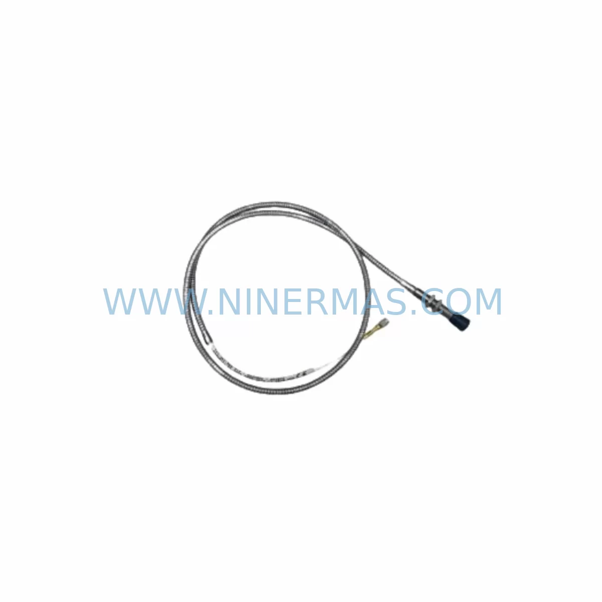
RFQ Ready
- SKU111-412-000-012
- CategoryTSI & Rotating Machinery Monitoring
- BrandVibro-Meter
- SupportAvailability, lead time, condition, and shipping coordination
How Buyers Usually Use This Page
- Confirm the exact part number and platform family before sending the quote request.
- Use direct email when quantity, condition, and destination are already defined internally.
- Switch to the broader brand or category archive when you need alternates nearby.
Series Navigation
Move through the most common platform families behind this part.
Product RFQ
Send this part directly for quotation.
Include quantity, required condition, destination country, and target delivery timing. Current reference: Vibro-Meter 111-412-000-012 Retrofit-Compatible Module for VM600 with SKU 111-412-000-012.
Vibro-Meter 111-412-000-012 Retrofit-Compatible Module for VM600: Legacy System Compatibility & Smooth Upgrade Path
The Vibro-Meter 111-412-000-012 is a precision vibration monitoring module designed for the VM600 series platform, widely deployed across power generation, petrochemical, and heavy industrial facilities. As original equipment manufacturers phase out legacy components, the 111-412-000-012 has become a critical retrofit and replacement solution for engineers tasked with extending the operational life of existing control architectures without committing to a full system overhaul.
NINERMAS maintains verified stock of the 111-412-000-012 and supports customers through the complete retrofit process — from pre-shipment compatibility verification to post-installation commissioning guidance. Every unit ships with a 12-month warranty and undergoes functional testing prior to dispatch.
Upgrade Compatibility Table
| Parameter | Details |
|---|---|
| SKU / Part Number | 111-412-000-012 |
| Brand / Manufacturer | Vibro-Meter |
| Compatible Platform | VM600 Series |
| Module Function | Vibration Signal Conditioning & Monitoring |
| Rack / Backplane Interface | VM600 standard backplane slot (verify slot addressing before installation) |
| Communication Compatibility | Compatible with VM600 internal communication bus; verify firmware revision alignment |
| Power Supply Requirement | Supplied via VM600 rack backplane; confirm rack PSU capacity before adding modules |
| Installation Space | Standard VM600 single-slot form factor; confirm physical clearance in existing cabinet |
| Replacement Recommendation | Direct replacement for discontinued 111-412-000-012 units; no hardware modification required in most configurations |
| Commissioning Notes | Verify channel address assignment, sensor input wiring, and alarm threshold configuration post-installation |
| Warranty | 12 Months from date of shipment |
Retrofit Planning for Existing Automation Systems
Replacing the 111-412-000-012 within an operational VM600-based monitoring system requires careful pre-planning to avoid unintended disruptions to adjacent channels and connected control loops. Before beginning the retrofit, engineers should document the existing wiring configuration at the terminal block level, noting sensor types (eddy-current probes, velocity transducers, or accelerometers), cable shielding practices, and signal polarity.
The VM600 rack accommodates multiple module types in a shared backplane architecture. When inserting or replacing the 111-412-000-012, it is essential to confirm that the VM600 rack power supply module — typically a dedicated PSU card within the same chassis — has sufficient headroom to support the additional or replacement load. Overloading the rack PSU is a common oversight during piecemeal upgrades and can cause intermittent resets across all installed cards.
For facilities running mixed-generation VM600 hardware, the 111-412-000-012 may coexist in the same rack with earlier-generation signal conditioning cards and later-revision communication interface modules. In such environments, the VM600 communication gateway module — responsible for transmitting vibration data upstream to the plant DCS or SCADA system — must be verified for protocol compatibility. Many sites operate Modbus RTU or Modbus TCP links between the VM600 system and a Siemens S7-series PLC or Allen-Bradley ControlLogix controller, and any module swap should be followed by a communication link integrity check.
Where the VM600 system feeds data into an HMI panel — whether a dedicated Vibro-Meter display unit or a third-party operator interface — the channel mapping and tag assignments within the HMI project should be reviewed. A replacement 111-412-000-012 installed in the same physical slot will typically retain its original channel address, but this must be confirmed through the VM600 configuration software before returning the system to automatic monitoring mode.
In control cabinets where space is constrained, the physical dimensions of the 111-412-000-012 and its connector orientation should be verified against the available slot clearance. Facilities that have added signal isolator modules or I/O terminal expansion blocks to the same cabinet may find that cable routing has changed since the original installation, requiring minor re-dressing of sensor cables before the new module can be seated cleanly.
For sites migrating from older Vibro-Meter hardware to a modernized VM600 platform, the 111-412-000-012 often serves as a bridging component — allowing the new rack infrastructure to interface with legacy eddy-current probe installations without requiring sensor replacement. This approach significantly reduces retrofit cost and installation time compared to a full sensor and cabling overhaul.
Downtime Control During System Migration
Minimizing unplanned downtime is the primary concern for any maintenance team undertaking a module replacement on a live vibration monitoring system. The 111-412-000-012 retrofit can typically be completed within a planned maintenance window if the following steps are observed.
First, export and archive the complete VM600 system configuration — including channel parameters, alarm setpoints, OK relay logic, and communication settings — before removing the existing module. This configuration backup ensures that if the replacement module requires re-initialization, all original parameters can be restored without relying on field memory or legacy documentation.
Second, coordinate with the control room to place the affected monitoring channels into bypass or inhibit mode prior to physical module removal. This prevents spurious trip signals from propagating to the plant protection system or DCS during the swap. If the VM600 system is integrated with a safety instrumented system (SIS) or hardwired to a turbine trip relay, the bypass procedure must be formally authorized under the site’s management of change (MOC) process.
Third, after installing the 111-412-000-012 and restoring power to the rack, perform a channel-by-channel verification of sensor readings against known reference values before releasing the channels from bypass. Pay particular attention to gap voltage readings on eddy-current channels, which confirm correct probe-to-target spacing and cable continuity. Any deviation from expected values should be investigated before the system is returned to automatic protection mode.
By following this structured approach, most 111-412-000-012 replacements can be completed with less than two hours of monitoring downtime, preserving plant control continuity and reducing the risk of post-maintenance incidents.
Retrofit Support FAQ
Q: Is the 111-412-000-012 a direct drop-in replacement for the original Vibro-Meter module of the same part number?
A: In the majority of VM600 installations, yes. The 111-412-000-012 is designed to occupy the same backplane slot and use the same terminal wiring as the original unit. However, customers should verify the firmware revision of the replacement module against the existing rack configuration, as certain VM600 firmware versions introduced changes to channel addressing and alarm output behavior. NINERMAS provides pre-shipment documentation to support this verification.
Q: What commissioning steps are required after installing the replacement module?
A: After physical installation, the minimum commissioning steps include: confirming channel address assignment in the VM600 configuration software, verifying sensor input signal levels (gap voltage, velocity, or acceleration as applicable), checking OK relay output status, and confirming that vibration data is being correctly received by the upstream DCS, SCADA, or HMI system. NINERMAS technical support can assist with commissioning guidance remotely.
Q: Does NINERMAS test the 111-412-000-012 before shipment?
A: Yes. All units supplied by NINERMAS undergo functional testing prior to dispatch. Each module is verified for correct power-up behavior, signal conditioning response, and communication output. A test report is available upon request. Units are shipped with protective packaging to prevent transit damage.
Q: What warranty and after-sales support does NINERMAS provide?
A: NINERMAS provides a 12-month warranty on all supplied 111-412-000-012 modules, covering manufacturing defects and functional failures under normal operating conditions. In the event of a warranty claim, NINERMAS will arrange replacement or repair. Ongoing technical support for installation, commissioning, and compatibility questions is available via email and phone throughout the warranty period.
| Product Series | Other series |
|---|
Catalog Continuation
More Vibro-Meter modules in the catalog.
Use the brand lane to compare nearby part numbers, platform-adjacent modules, and other inquiry-ready listings before sending your final RFQ.
SKU: 204-900-000-011
Vibro-meter 204-900-000-011 Safety-Reliable Vibration Monitor
SKU: GSI127 244-127-000-017 A1-B02
Vibro-Meter GSI127 244-127-000-017 A1-B02 Service-Ready Spare Part
SKU: VM600 MPC4 200-510-041-021
VIBRO-METER VM600 MPC4 200-510-041-021 Safety Machinery Protection
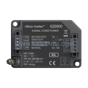
SKU: IQS900 204-900-000-011 A1-B21-C1-H10-I0
VIBRO-METER IQS900 204-900-000-011 Safety-Reliable Vibration Monitor
Catalog Continuation
Alternative parts within TSI & Rotating Machinery Monitoring.
Stay inside the same system family when you need substitutes, adjacent modules, or a broader shortlist for procurement review.
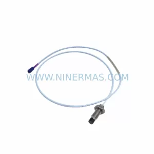
SKU: 330703-000-060-90-02-00
Bently Nevada 330703-000-060-90-02-00 Retrofit Module
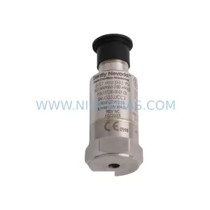
SKU: 177230-00-01-CN 16925-33
Bently Nevada 177230-00-01-CN 16925-33 Service-Ready Spare Part for Industrial Maintenance
SKU: 330904-00-09-10-02-05/CN
Bently Nevada 330904-00-09-10-02-05/CN Safety-Reliable Vibration Monitor