Original Industrial Spare Part
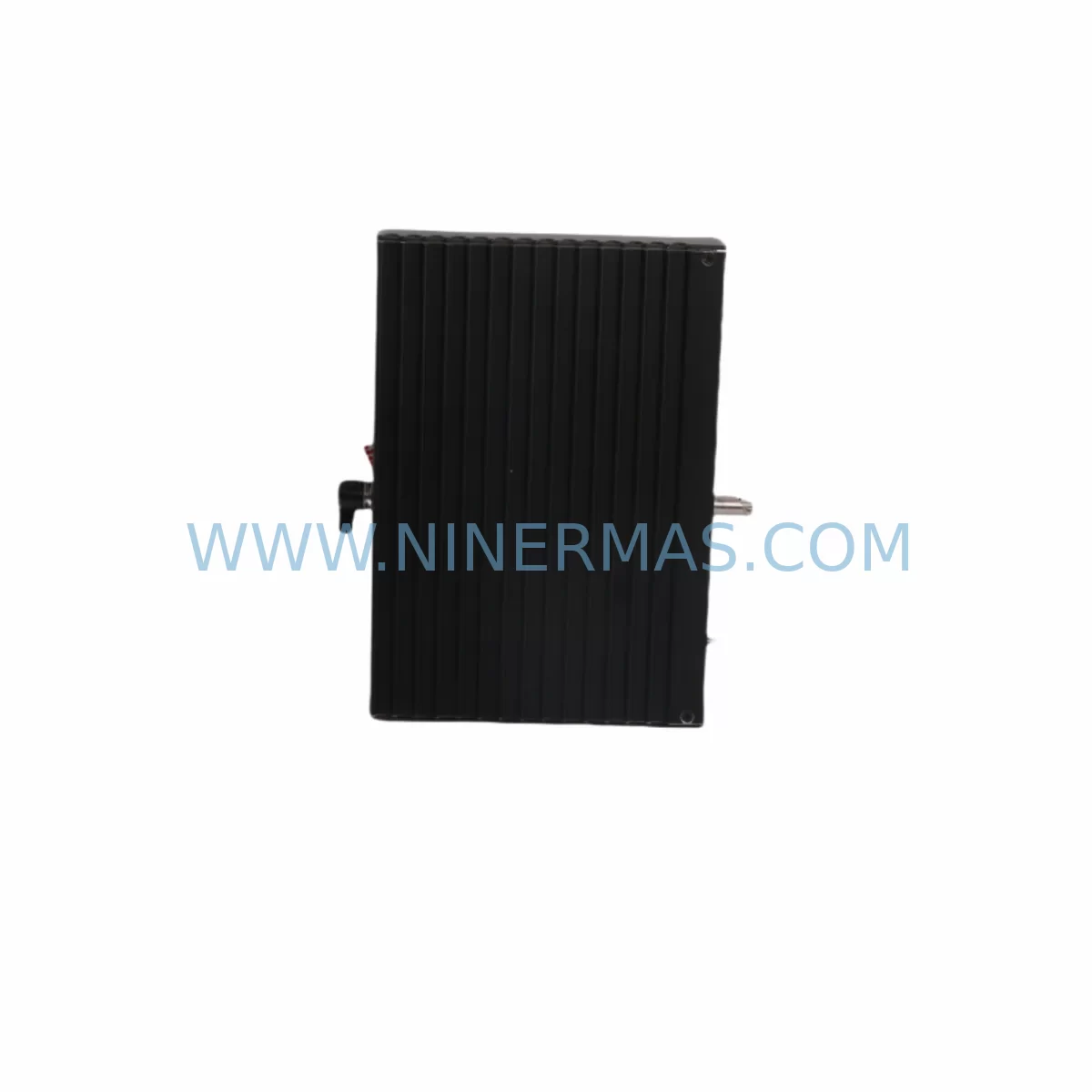
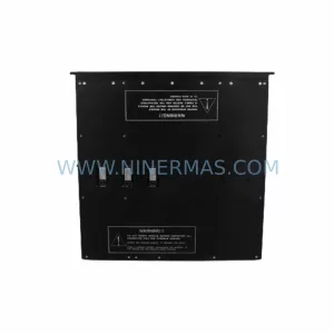
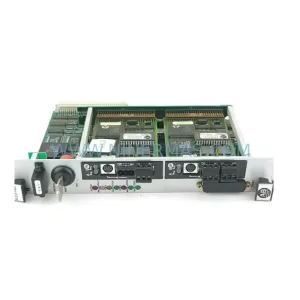
Triconex RO3451 Retrofit Relay Output for Legacy Systems
Verify the part, confirm the platform family, and move straight into quotation with the right commercial details.
RFQ Ready
- SKURO3451
- CategorySIS Safety & Redundancy Systems
- BrandTRICONEX
- SupportAvailability, lead time, condition, and shipping coordination
How Buyers Usually Use This Page
- Confirm the exact part number and platform family before sending the quote request.
- Use direct email when quantity, condition, and destination are already defined internally.
- Switch to the broader brand or category archive when you need alternates nearby.
Series Navigation
Move through the most common platform families behind this part.
Product RFQ
Send this part directly for quotation.
Include quantity, required condition, destination country, and target delivery timing. Current reference: Triconex RO3451 Retrofit Relay Output for Legacy Systems with SKU RO3451.
Triconex RO3451 Retrofit Relay Output for Legacy Systems
The Triconex RO3451 is a ruggedized relay output module engineered for the Tricon Triple Modular Redundant (TMR) safety system platform — one of the most widely deployed safety-rated control architectures in oil and gas, petrochemical, power generation, and continuous process industries. As original equipment manufacturers phase out legacy Tricon hardware and end-of-life notices accumulate, the RO3451 has become a critical retrofit component for facilities that must maintain operational continuity without committing to a full DCS or SIS migration. This module provides 16 relay output channels with isolated contacts, designed to interface directly with field actuators, solenoid valves, motor starters, and alarm annunciators in safety-critical loops.
For maintenance engineers managing aging Tricon cabinets, the RO3451 represents a direct, slot-compatible replacement for earlier relay output variants. Its physical form factor matches the standard Tricon I/O chassis backplane, allowing installation without modification to the existing rack structure. Before proceeding with a swap, engineers should verify the chassis slot assignment, confirm the module address configuration in the TriStation 1131 programming environment, and review the relay contact rating against the field load specifications documented in the original loop drawings.
Upgrade Compatibility Table
| Parameter | RO3451 (Current) | Legacy Relay Output Variants | Retrofit Notes |
|---|---|---|---|
| Output Channels | 16 relay outputs | 8–16 channels (model-dependent) | Verify channel count matches loop list |
| Contact Rating | 2A @ 30VDC / 0.5A @ 125VAC | Varies by revision | Check field load current draw before swap |
| Backplane Interface | Tricon standard I/O bus | Tricon standard I/O bus | Direct slot-compatible; no adapter required |
| Module Addressing | Configured via TriStation 1131 | Same platform | Re-download configuration after installation |
| Communication Protocol | Tricon internal TMR bus | Tricon internal TMR bus | No protocol migration required |
| Installation Space | Standard Tricon I/O slot | Same form factor | Confirm slot availability in chassis |
| Terminal Wiring | Field terminal panel (4119A-type) | Same terminal panel | Inspect terminal torque and wire condition |
| Pre-Shipment Testing | Full functional test performed | N/A (new OEM) | Test report available on request |
| Warranty | 12-Month Warranty — All units tested and verified before dispatch | ||
Retrofit Planning for Existing Automation Systems
A successful RO3451 retrofit begins well before the module arrives on site. The first step is a thorough audit of the existing Tricon chassis — typically a 3625 I/O chassis or equivalent — to confirm available slot positions, backplane bus integrity, and power budget. The Tricon PS3451 power supply module must be assessed to ensure it can sustain the additional relay coil energization load introduced by the replacement module, particularly in high-density output configurations where multiple relay channels switch simultaneously.
Wiring continuity is the next critical checkpoint. The RO3451 connects to field devices through a dedicated terminal panel — commonly a 4119A-type terminal assembly — which must be inspected for corrosion, loose terminations, and correct wire labeling before the new module is seated. In facilities where the original wiring documentation is incomplete or outdated, a point-to-point continuity check against the as-built loop drawings is strongly recommended prior to energization.
On the software side, the TriStation 1131 programming environment must be used to verify that the module’s slot address, I/O variable assignments, and safety function logic remain intact after the physical swap. Engineers should export a full project backup before any hardware change and confirm that the Tricon MP3101 main processor recognizes the new module without generating diagnostic faults. If the system includes a Tricon 8312 communication module for Modbus or DCS integration, the communication link should be tested end-to-end after the relay output module is reinstalled to confirm that the supervisory control layer continues to receive correct status feedback.
For facilities running parallel HMI systems — whether legacy Wonderware, FactoryTalk, or a modern SCADA platform — the HMI graphic associated with the relay output points should be validated to confirm that the display reflects the correct ON/OFF state after the module replacement. Any discrepancy between the HMI indication and the physical relay state must be resolved before returning the loop to automatic control. In some installations, the Tricon 2481 HMI interface card or equivalent communication bridge may require a soft reset to re-establish the data exchange after a module change.
I/O expansion scenarios — where the RO3451 is being added to a chassis that previously had fewer relay output points — require additional planning. The Tricon 3503E digital input module in adjacent slots should be checked for address conflicts, and the TriStation project must be updated to include the new I/O variable declarations before the expanded configuration is downloaded to the controller. A Triconex programming cable (model 4200 or equivalent USB-to-serial adapter) is required for the configuration download if the system does not support Ethernet-based programming access.
Signal isolation requirements should also be reviewed during the retrofit planning phase. In applications where the relay outputs drive inductive loads such as solenoid valves or motor contactors, transient suppression devices — either integrated into the terminal panel or added externally — protect the relay contacts from voltage spikes that can accelerate contact wear and reduce module service life. The Triconex AI3351 analog input module in the same cabinet should be checked for any ground loop issues that may be introduced when relay contact wiring is modified.
Downtime Control During System Migration
Minimizing unplanned downtime during a relay output module replacement requires a structured pre-outage preparation protocol. The maintenance window should be scheduled during a planned production pause, with the control system placed in manual override mode to maintain field device states while the Tricon chassis is partially de-energized. The original program logic — including all safety function blocks, cause-and-effect matrices, and interlock configurations — must be preserved in a verified TriStation project backup stored on an isolated engineering workstation before any hardware is disturbed.
During the physical swap, the Tricon TMR architecture provides a degree of fault tolerance that can allow continued operation in degraded mode while a single I/O module is replaced, depending on the system configuration and the safety integrity level requirements of the specific loop. Engineers should consult the Tricon system documentation and the site-specific safety requirements specification before relying on this capability in a live environment.
After the RO3451 is seated and the terminal connections are verified, the module should be powered up with the TriStation diagnostic display active to confirm that all three TMR legs recognize the module without fault. The relay output channels should be exercised individually using the TriStation force function — with appropriate permit-to-work controls in place — before the system is returned to automatic control. Total commissioning time for a single module replacement in a well-documented system is typically two to four hours, including wiring verification, software download, and functional testing.
Retrofit Support FAQ
Q1: Is the RO3451 a direct replacement for earlier Triconex relay output modules?
The RO3451 is slot-compatible with the standard Tricon I/O chassis and uses the same backplane interface as earlier relay output variants. In most installations, it can be installed in the same slot without chassis modification. However, the module address and I/O variable assignments must be verified in TriStation 1131 before the replacement is commissioned, as software configuration differences between module revisions can affect diagnostic behavior.
Q2: What commissioning steps are required after installing the RO3451?
After physical installation, the TriStation 1131 project should be downloaded to the Tricon MP3101 main processor to confirm module recognition. Each relay output channel should be individually tested using the TriStation force function under permit-to-work conditions. The terminal panel wiring should be verified for correct torque and continuity, and the HMI display should be checked to confirm correct status indication for all affected output points.
Q3: How is wiring compatibility confirmed before the module swap?
The existing terminal panel — typically a 4119A-type assembly — should be inspected against the original loop drawings to confirm wire labeling, terminal assignment, and contact rating compatibility. The relay contact specifications of the RO3451 (2A @ 30VDC / 0.5A @ 125VAC) must be compared against the field load current draw for each connected device. Any wiring discrepancies should be corrected before the new module is energized.
Q4: What warranty and pre-shipment testing does the RO3451 include?
All RO3451 units supplied by NINERMAS are functionally tested before dispatch. A 12-month warranty is included as standard, covering defects in materials and workmanship under normal operating conditions. Test reports are available on request. Units are shipped with appropriate ESD protection and packaging to prevent transit damage. In-stock units are typically available for same-week dispatch to minimize system downtime.
| Product Series | Tricon |
|---|---|
| Country of Origin | US |
Catalog Continuation
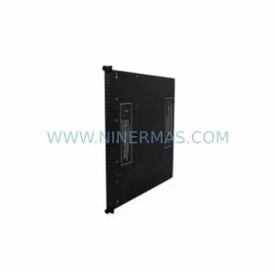
Likely Triconex platform matches.
These parts are closer to the same platform family signaled by the current SKU and title, so buyers can validate continuity before sending a final RFQ.
Catalog Continuation
Nearby part numbers around RO3451.
Use this lane when the buyer is comparing adjacent model numbers, revision-near items, or closely related spare variants within the same brand family.
Catalog Continuation
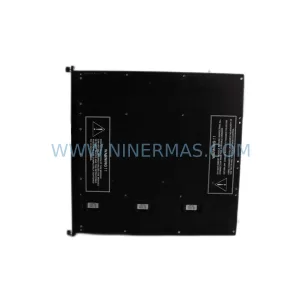
More TRICONEX modules in the catalog.
Use the brand lane to compare nearby part numbers, platform-adjacent modules, and other inquiry-ready listings before sending your final RFQ.
Catalog Continuation
Alternative parts within SIS Safety & Redundancy Systems.
Stay inside the same system family when you need substitutes, adjacent modules, or a broader shortlist for procurement review.
SKU: IS200BPVCG1BR1
GE IS200BPVCG1BR1 Safety-Reliable Board for Critical Control
SKU: FC-SCNT02 FC-TCNT11 FC-SCNT01 FC-SSWM01 .CC-SDRX01
Honeywell FC-SCNT02 Retrofit-Compatible Safety Controller Node
SKU: G85139-H1750-C810-D
Siemens G85139-H1750-C810-D Safety-Reliable Drive Module