Original Industrial Spare Part
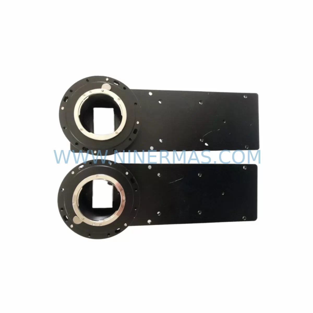
SVS-Vistek HR16000MTLCPC Retrofit CCD Camera for Legacy Systems
Verify the part, confirm the platform family, and move straight into quotation with the right commercial details.
RFQ Ready
- SKUHR16000MTLCPC
- CategoryPLC & Industrial Automation Modules
- BrandSVS-Vistek
- SupportAvailability, lead time, condition, and shipping coordination
How Buyers Usually Use This Page
- Confirm the exact part number and platform family before sending the quote request.
- Use direct email when quantity, condition, and destination are already defined internally.
- Switch to the broader brand or category archive when you need alternates nearby.
Series Navigation
Move through the most common platform families behind this part.
Product RFQ
Send this part directly for quotation.
Include quantity, required condition, destination country, and target delivery timing. Current reference: SVS-Vistek HR16000MTLCPC Retrofit CCD Camera for Legacy Systems with SKU HR16000MTLCPC.
SVS-Vistek HR16000MTLCPC Retrofit CCD Camera for Legacy Systems
The SVS-Vistek HR16000MTLCPC is a high-resolution CCD area scan camera engineered for demanding industrial machine vision applications. As production lines age and original equipment manufacturers discontinue legacy imaging components, the HR16000MTLCPC has become a critical retrofit solution for facilities operating older inspection, measurement, and quality control systems. With its 16-megapixel CCD sensor, Camera Link interface, and robust industrial housing, this camera delivers a direct upgrade path for systems previously built around discontinued or end-of-life imaging hardware — without requiring a complete platform overhaul.
For maintenance engineers and automation specialists managing legacy vision systems, the HR16000MTLCPC offers a proven compatibility bridge. Whether your facility runs an aging SVCam-EXO series setup, an older HR11002MTLCPC-based inspection cell, or a Camera Link frame grabber platform that predates GigE migration, this camera integrates into existing control cabinet architectures with minimal rewiring and no PLC logic changes in most cases.
Upgrade Compatibility Table
| Parameter | HR16000MTLCPC Specification | Retrofit Notes |
|---|---|---|
| Sensor Type | CCD, 16 MP (4872 × 3248) | Direct replacement for legacy 12–16 MP CCD platforms |
| Interface | Camera Link (Full Configuration) | Compatible with existing Camera Link frame grabbers (e.g., Matrox Solios, Euresys Grablink) |
| Pixel Size | 7.4 µm × 7.4 µm | Verify lens magnification and working distance before swap |
| Frame Rate | Up to 3.75 fps (full res) | Confirm trigger timing with existing PLC or motion controller |
| Power Supply | 12 VDC via Camera Link connector | Check cabinet power rail capacity; no separate PSU required |
| Mounting | C-Mount / F-Mount adapter available | Confirm lens mount compatibility before installation |
| Operating Temp | 0°C to +50°C | Verify cabinet thermal management for enclosed installations |
| Communication | Camera Link serial (CLSerial) | Update frame grabber driver and SDK if migrating from older SVS-Vistek firmware |
| Replacement Path | HR11002MTLCPC, HR29050MTLCPC, legacy SVCam-HR series | Pixel-level recalibration required after swap |
| Warranty | 12 Months | Covered from date of shipment; includes DOA exchange |
Retrofit Planning for Existing Automation Systems
A successful HR16000MTLCPC retrofit begins well before the camera arrives on-site. Engineers must audit the existing vision station to confirm that the installed Camera Link frame grabber — whether a legacy Matrox Meteor II/CL, an Euresys Grablink Full, or a National Instruments PCIe-1433 — supports the Full Camera Link configuration required by the HR16000MTLCPC. Partial or Base configuration frame grabbers will not expose the full sensor bandwidth and must be upgraded or replaced before commissioning.
Terminal wiring is the next critical checkpoint. The HR16000MTLCPC uses a standard 26-pin MDR Camera Link connector on both the camera and frame grabber ends. If the legacy system used a different pinout or a proprietary cable assembly from an older SVCam-EXO or SVCam-STD installation, replacement Camera Link cables rated for the full MDR-to-MDR configuration must be sourced. Cable length should not exceed 10 metres for reliable signal integrity at full resolution; for longer runs, consider a Camera Link repeater or fibre extender module.
Backplane and rack space confirmation is equally important in retrofit scenarios. The HR16000MTLCPC’s compact C-mount body fits most standard camera mounting brackets, but facilities upgrading from larger-format cameras — such as the HR29050MTLCPC or older line-scan models — may need to fabricate new mounting plates or adjust the optical axis height. Confirm the installation envelope, including lens protrusion and cable bend radius, before scheduling the maintenance window.
For systems that previously relied on hardware trigger signals routed through a dedicated trigger distribution module or a Beckhoff EtherCAT I/O terminal, the HR16000MTLCPC’s trigger input (opto-isolated, 5–24 VDC) is directly compatible with standard PLC digital output cards. No signal conditioning is required in most cases, though engineers should verify the trigger pulse width meets the camera’s minimum exposure gate requirement — typically 10 µs or greater.
Where the legacy vision system included an HMI display panel showing live camera feeds via a dedicated frame grabber output, the HR16000MTLCPC retrofit may require updating the HMI image acquisition driver or vision software configuration (e.g., Cognex VisionPro, Halcon, or NI Vision) to recognise the new camera’s resolution and pixel format. This is a software-only change in most platforms and does not affect the underlying PLC ladder logic or motion control program.
Signal isolation between the camera trigger circuit and the main control cabinet I/O bus is recommended for installations in electrically noisy environments — particularly those involving servo drives, variable frequency drives, or high-current switching equipment. A DIN-rail-mounted signal isolator module inserted between the PLC output and the camera trigger input will protect the camera’s opto-isolator from voltage spikes and ground loops that are common in retrofit environments.
Finally, engineers should confirm that the vision software licence covers the HR16000MTLCPC’s sensor resolution. Some legacy vision platform licences are resolution-capped, and upgrading from a 5 MP or 8 MP camera to the 16 MP HR16000MTLCPC may require a licence upgrade from the software vendor before the system can operate at full resolution.
Downtime Control During System Migration
Minimising production downtime during a camera retrofit requires a structured pre-commissioning protocol. The recommended approach is to complete all software configuration, driver updates, and frame grabber parameter adjustments on a bench test rig before the scheduled maintenance window. This includes loading the HR16000MTLCPC’s camera descriptor file into the frame grabber configuration utility, verifying the pixel clock and tap geometry settings, and confirming that the vision software can acquire a stable live image at full resolution.
During the actual swap, the original camera and cable assembly should be retained and labelled — not discarded — until the replacement system has passed a full production acceptance test. This preserves the option to revert to the legacy configuration if an unexpected compatibility issue arises during commissioning. In most HR16000MTLCPC retrofit cases, the physical swap, cable reconnection, and initial image acquisition can be completed within a two-hour maintenance window, provided the pre-commissioning steps have been completed in advance.
Protecting the original PLC program logic is non-negotiable. The camera retrofit should not require any changes to the PLC’s main control program. Vision system outputs — pass/fail signals, measurement data, alarm triggers — should continue to interface with the PLC via the same I/O addresses and communication protocol as before. If the legacy system used a serial RS-232 link between the vision controller and the PLC, confirm that the replacement vision PC or smart camera supports the same baud rate and data format before go-live.
Post-installation, a calibration run using the facility’s standard calibration target is mandatory. The HR16000MTLCPC’s 7.4 µm pixel pitch may produce slightly different measurement results compared to the legacy camera, particularly if the original system was calibrated with a different pixel size. A full pixel-to-millimetre recalibration, followed by a golden sample verification run, ensures measurement continuity and prevents false rejects or missed defects in the first production shift after retrofit.
Retrofit Support FAQ
Q1: Is the HR16000MTLCPC a direct drop-in replacement for the HR11002MTLCPC?
A: The HR16000MTLCPC uses the same Camera Link Full interface and C-mount lens mount as the HR11002MTLCPC, making it physically compatible with most existing installations. However, the higher resolution (16 MP vs. 11 MP) requires updating the frame grabber’s camera descriptor file and recalibrating the vision application. The camera body dimensions are identical, so no mechanical modifications are required.
Q2: What pre-shipment testing is performed on the HR16000MTLCPC?
A: Each unit undergoes a full functional test including sensor uniformity verification, dark current measurement, trigger response confirmation, and Camera Link signal integrity check before shipment. A test report is available upon request. Units are shipped in anti-static packaging with protective lens cap installed.
Q3: Can the HR16000MTLCPC operate with our existing Camera Link cables and frame grabber?
A: In most cases, yes — provided the frame grabber supports Camera Link Full configuration and the cables are standard MDR-26 assemblies in good condition. Cables longer than 10 metres or cables with damaged shielding should be replaced to ensure reliable operation at the HR16000MTLCPC’s full pixel clock rate. Contact our technical team with your frame grabber model number for a compatibility confirmation before ordering.
Q4: What does the 12-month warranty cover?
A: The 12-month warranty covers manufacturing defects, sensor failures, and interface faults under normal operating conditions. It includes a DOA (Dead on Arrival) exchange within 7 days of receipt and a repair-or-replace service for warranty claims submitted within the coverage period. The warranty does not cover physical damage, ESD damage, or failures resulting from operation outside the specified environmental conditions. Warranty service is coordinated directly through NINERMAS with no requirement to return the unit to the original manufacturer.
| Product Series | Legacy |
|---|
Catalog Continuation
Alternative parts within PLC & Industrial Automation Modules.
Stay inside the same system family when you need substitutes, adjacent modules, or a broader shortlist for procurement review.