Siemens V23012-A0133-B001 Industrial Relay Module | Automation Control Switching Solution
Description
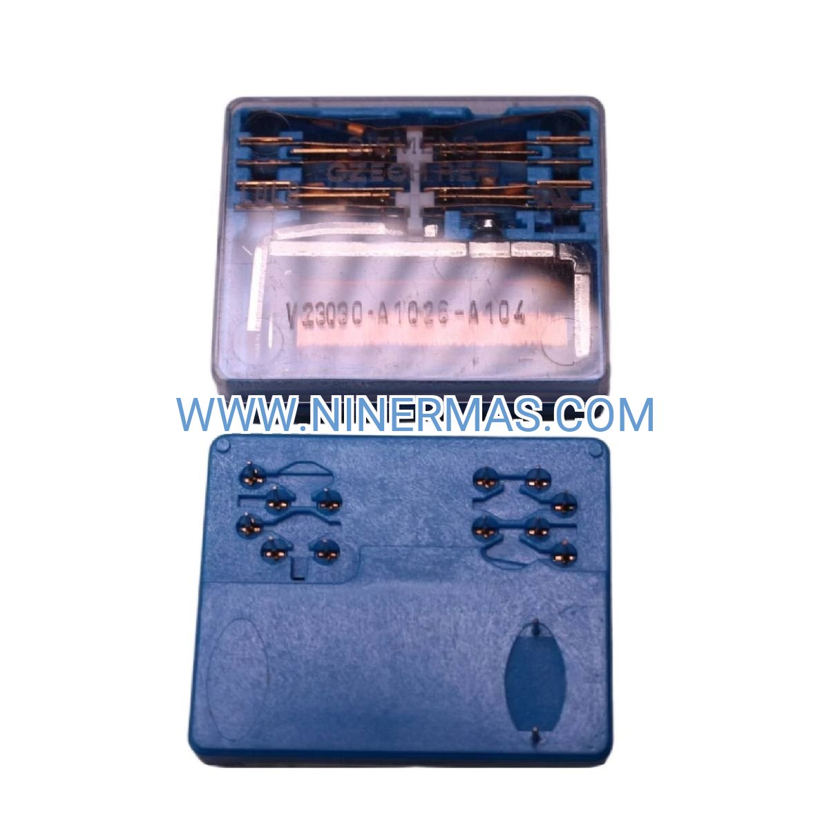
Siemens V23012-A0133-B001 Industrial Relay Module (High-Reliability Automation Control Solution)
The Siemens V23012-A0133-B001 is an industrial-grade relay module engineered for automation control systems, delivering precise switching control through advanced electromagnetic design. This module integrates seamlessly with PLC, DCS, and SCADA architectures to enable reliable signal isolation, load switching, and circuit protection across demanding industrial environments.
Designed for manufacturing automation, process control, and building management systems, this relay module addresses critical challenges including contact bounce, electrical noise interference, inductive load switching stress, and system downtime caused by component failure. It serves design engineers, system integrators, panel builders, and maintenance teams across energy, chemical processing, water treatment, and discrete manufacturing sectors.
Through standardized mounting configurations and customizable wiring options, the V23012-A0133-B001 offers fast commissioning, long service life, excellent EMC performance, and broad compatibility with global control standards. Contact our engineering team for application-specific selection guidance, technical datasheets, and competitive quotations.
Core Features & Technical Advantages
- High-Reliability Contact System
Utilizes silver alloy contacts with optimized spring force design, ensuring stable switching performance across 100,000+ mechanical cycles. Minimizes contact degradation and false triggering in high-frequency switching applications. - Wide Voltage Compatibility
Supports multiple coil voltage ratings (DC 12V/24V/48V, AC 24V/110V/230V options available), enabling flexible integration with diverse control power supplies and reducing inventory complexity for multi-project deployments. - Compact DIN-Rail Mounting
Standard 35mm DIN-rail compatible housing with tool-free clip installation, saving panel space and accelerating assembly time. Ideal for high-density control cabinet layouts and retrofit projects. - Comprehensive Protection Features
Equipped with coil surge suppression, arc quenching chambers, and thermal overload protection. Reduces damage from voltage spikes, inductive kickback, and abnormal operating conditions, extending mean time between failures (MTBF). - Clear Status Indication
Integrated mechanical position indicator or optional LED status display provides instant visual confirmation of relay state, simplifying troubleshooting and reducing commissioning errors during system startup. - Industrial-Grade Environmental Resistance
Operates reliably in -25°C to +55°C ambient temperatures with IP20 protection rating (IP40 optional). Resistant to vibration, humidity, and dust contamination typical in factory floors and outdoor enclosures.
Typical Application Scenarios
This relay module is engineered for applications demanding high switching reliability, electrical isolation, and long-term operational stability, particularly in:
- PLC & DCS Control Panels
Provides galvanic isolation between low-voltage control signals and high-power actuators (motors, valves, heaters), protecting sensitive PLC I/O modules from voltage transients and ground loop interference. - Motor Control & VFD Interfacing
Enables safe start/stop control for pumps, fans, conveyors, and variable frequency drives. Handles inductive load switching with minimal contact wear, suitable for HVAC systems, water treatment plants, and material handling equipment. - Process Automation & Safety Circuits
Integrates into emergency stop chains, interlock logic, and alarm systems within chemical processing, pharmaceutical manufacturing, and food & beverage production lines, meeting IEC 61508 functional safety requirements. - Building Automation & Energy Management
Controls lighting circuits, HVAC dampers, and power distribution switching in commercial buildings, data centers, and smart grid applications. Supports remote monitoring integration via BMS/BAS protocols. - Test & Measurement Equipment
Serves as signal routing switches in automated test benches, calibration systems, and quality inspection stations, where contact cleanliness and switching repeatability are critical for measurement accuracy.
Technical Specifications & Selection Guide
To facilitate engineering design and procurement, we provide key electrical and mechanical parameters below. Custom configurations are available for OEM projects and large-scale deployments.
| Parameter | Specification |
|---|---|
| Model Number | V23012-A0133-B001 |
| Contact Configuration | SPDT / DPDT (verify datasheet for exact type) |
| Coil Voltage Range | DC 12V / 24V / 48V (specify when ordering) |
| Contact Rating | 10A @ 250VAC / 10A @ 30VDC (resistive load) |
| Switching Capacity | 2500VA (AC) / 300W (DC) |
| Mechanical Life | 10 million operations (no load) |
| Electrical Life | 100,000 operations (rated load) |
| Operating Temperature | -25°C to +55°C |
| Protection Rating | IP20 (standard) / IP40 (optional) |
| Mounting Method | 35mm DIN-rail or screw terminal base |
| Compliance Standards | IEC 61810, UL 508, CE marked |
| Dimensions (W×H×D) | Approx. 45mm × 75mm × 90mm (verify datasheet) |
Selection Recommendations: When specifying this relay module, consider the following factors: maximum switching current and voltage of the controlled load, coil voltage compatibility with your control power supply, required contact configuration (NO/NC/changeover), ambient temperature and enclosure IP rating at installation site, and available mounting space within the control panel. For assistance with application-specific selection, please provide load type (resistive/inductive/capacitive), switching frequency, and environmental conditions—our engineers will recommend the optimal configuration and provide certified technical documentation.
Extended Functionality & Integration Options
- Modular Accessory Compatibility
Supports plug-in surge suppressors, manual test buttons, and LED indicator modules for enhanced diagnostics and protection. Accessories mount directly onto relay base without additional wiring. - Communication Protocol Integration
Can be integrated into distributed I/O systems via relay output modules supporting Modbus RTU, PROFIBUS DP, or EtherNet/IP protocols, enabling remote monitoring and control through SCADA platforms. - Customization for OEM Projects
Available with custom coil voltages, contact materials (gold-plated for low-level signals), and special terminal configurations. Minimum order quantities apply for customized variants—consult engineering for feasibility and lead times.
Delivery, Service & Quality Assurance
Lead Time: Standard catalog items ship within 3–5 business days from stock. Custom-configured relays require 15–25 days depending on specification complexity and order volume.
Warranty: All Siemens relay modules are covered by a 12-month manufacturer warranty against defects in materials and workmanship. Extended warranty programs available for critical applications.
Technical Support: We provide remote technical consultation for application design, wiring diagrams, and troubleshooting assistance. On-site commissioning support available in select regions (subject to service agreement).
Documentation Package: Each shipment includes product datasheet, dimensional drawings, wiring diagrams, and compliance certificates (CE/UL/IEC). CAD models and EPLAN macros available upon request for panel design integration.
Quality Certifications: Manufactured under ISO 9001 quality management system. Products undergo 100% functional testing including contact resistance measurement, insulation voltage testing, and coil pull-in/drop-out verification before shipment.
Frequently Asked Questions (FAQ)
Q: How do I interface the Siemens V23012-A0133-B001 relay module with my existing PLC system?
A: Connect the relay coil terminals to your PLC's digital output (DO) module, ensuring coil voltage matches the PLC output rating (typically 24VDC). Use the relay's NO/NC contacts to switch your external load circuit. Always install a flyback diode across the coil for DC applications to protect the PLC output from inductive kickback. Refer to the wiring diagram in the product datasheet for detailed connection schematics.
Q: What is the maximum number of relays I can control from a single PLC output?
A: This depends on your PLC output current capacity and the relay coil current draw. For example, if your PLC output provides 500mA and each relay coil draws 50mA, you can theoretically control up to 10 relays in parallel. However, we recommend staying below 80% of the rated output current and using relay driver modules or solid-state outputs for controlling multiple relays to ensure reliable operation.
Q: Can this relay module handle inductive loads like motors and solenoid valves?
A: Yes, the V23012-A0133-B001 is designed to switch inductive loads. However, inductive loads generate voltage spikes during switching, which can reduce contact life. We recommend installing RC snubber circuits or varistor suppressors across the load to minimize arcing. For highly inductive loads (power factor < 0.4), derate the contact current to 60–70% of the resistive rating to ensure long service life.
Q: What is the IP protection rating, and can it be used in outdoor or dusty environments?
A: The standard version offers IP20 protection, suitable for clean indoor control cabinets. For outdoor installations or dusty industrial environments, specify the IP40 variant or install the relay inside a sealed enclosure rated IP54 or higher. Ensure adequate ventilation to prevent heat buildup, especially when switching high currents.
Q: Does this relay support remote monitoring or provide feedback signals?
A: The relay itself is an electromechanical switching device without built-in communication capability. However, you can monitor its status by reading the PLC input connected to an auxiliary contact (if available on your relay model) or by using relay output modules with integrated diagnostics that communicate via Modbus, PROFIBUS, or EtherNet/IP protocols. Contact our engineering team to discuss remote monitoring solutions for your specific application.
Q: What is the expected lifespan, and how often should relays be replaced in critical systems?
A: Mechanical life exceeds 10 million operations under no-load conditions, while electrical life is rated at 100,000 operations at full load. Actual lifespan depends on switching frequency, load type, and environmental conditions. For critical safety or production systems, we recommend implementing predictive maintenance schedules based on cycle counters or replacing relays every 3–5 years as a preventive measure, even if no failure symptoms are observed.
Request Technical Support & Quotation
To receive detailed application guidance, certified datasheets, or project-specific pricing, please provide the following information: project name and application type, load specifications (voltage, current, power factor), required contact configuration and quantity, coil voltage and control signal type, operating environment (temperature, humidity, IP rating), and estimated annual volume. Our engineering team will respond within 24 hours with tailored recommendations and competitive quotations.
© 2026 NINERMAS COMPANY LIMITED. All rights reserved. Original Source: https://ninermas.com | Contact: sale@ninermas.com | +0086 187 5021 5667


Contact Info
-
Address:22 / F, South Wo Hang building, 148 Wing Lok Street, Sheung Wan, Western District, Hong Kong
-
Phone:+8618750215667
-
Email: