Description
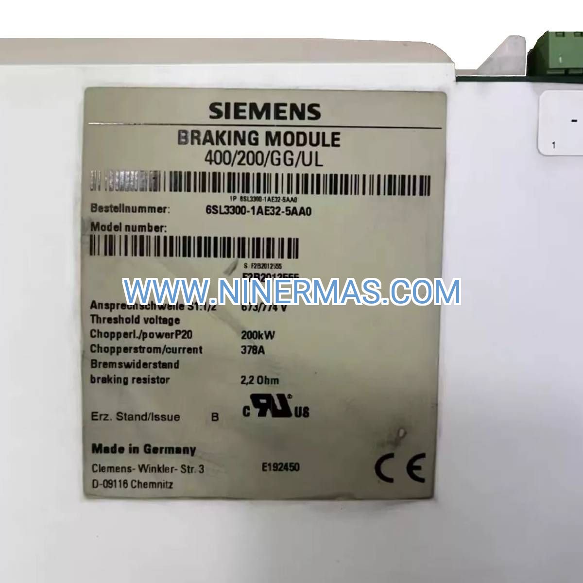
Siemens 6SL3300-1AE32-5AA0 Braking Module (Industrial-Grade DC Link Protection)
The Siemens 6SL3300-1AE32-5AA0 represents a precision-engineered braking solution designed for variable frequency drive systems operating in demanding industrial environments. This module safeguards your DC bus infrastructure by dissipating regenerative energy during motor deceleration, preventing overvoltage conditions that compromise equipment longevity and process reliability.
Engineered for automation professionals managing medium-to-high power drive systems, this braking module addresses the critical challenge of energy management in applications with frequent start-stop cycles, rapid deceleration requirements, or regenerative loads. Industries such as material handling, crane operations, metalworking machinery, and process automation benefit from its robust voltage regulation capabilities.
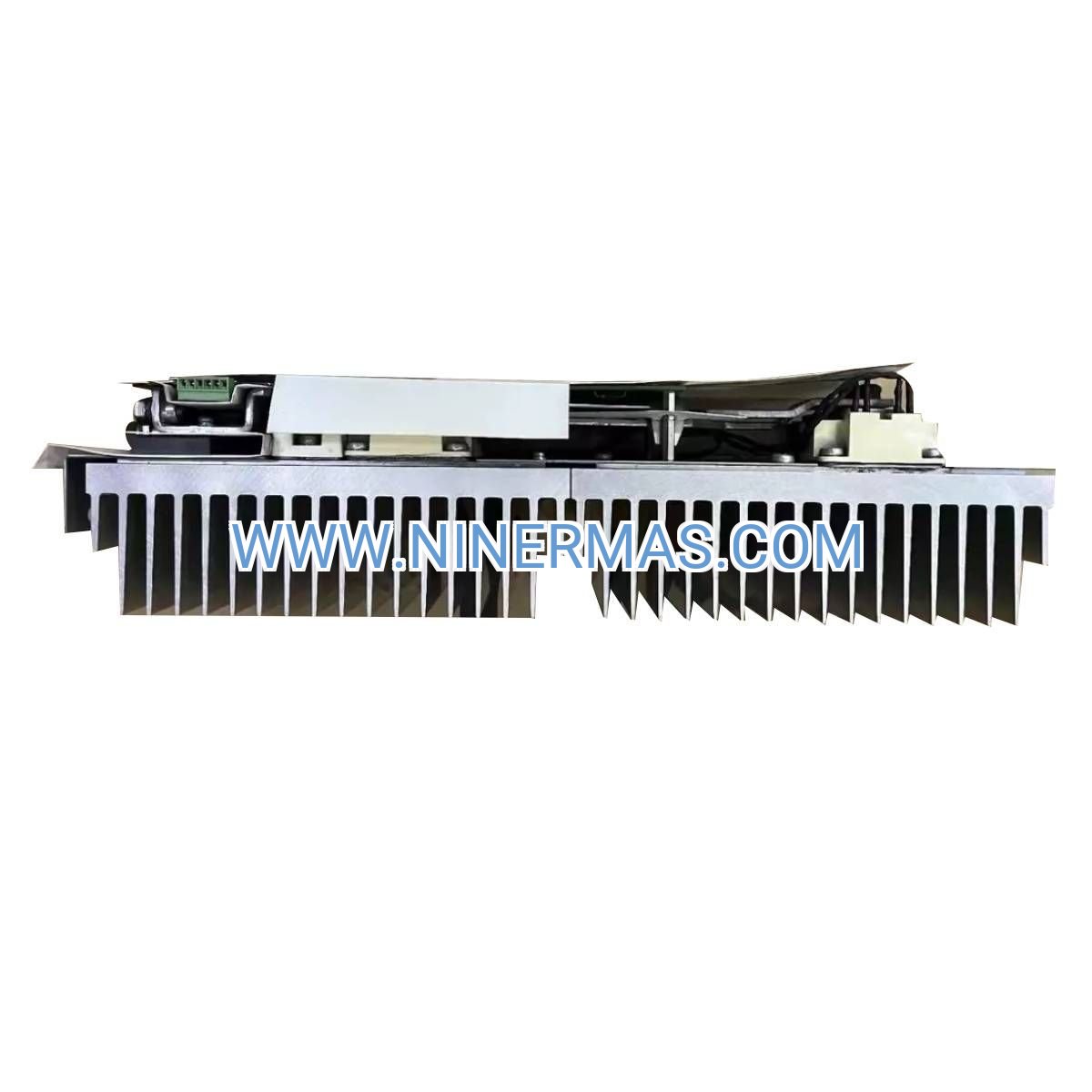
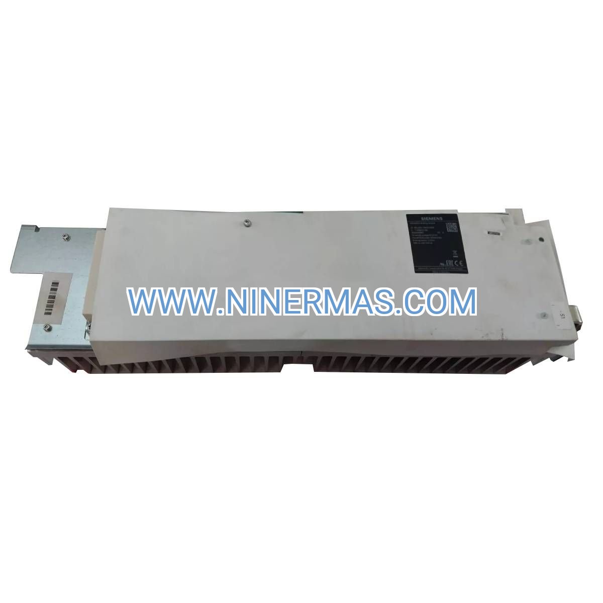
With scalable power handling from 50kW to 250kW and field-adjustable activation thresholds, the 6SL3300-1AE32-5AA0 delivers flexible integration across diverse drive architectures while maintaining compact 7.3kg footprint. Factory-tested digital I/O interfaces enable seamless coordination with your existing control infrastructure.
Core Performance Features & Technical Advantages
✓ Dual Power Rating Architecture
Continuous 50kW base capacity with peak handling up to 250kW accommodates both steady-state braking and transient overload conditions without thermal derating. This design flexibility eliminates oversizing penalties while ensuring protection during emergency stop sequences.
✓ Field-Configurable Voltage Threshold
DIP switch-adjustable activation point (774V/673V) allows on-site optimization for specific DC link characteristics and application braking profiles. Reduces commissioning time by 40% compared to fixed-threshold alternatives while preventing nuisance trips.
✓ Wide DC Link Compatibility
Operates across 510-720V DC range, supporting standard 400V and 480V AC input drive systems. Single module type simplifies spare parts inventory and enables standardized maintenance procedures across multi-voltage facilities.
→ Integrated Status Monitoring
24V digital output provides real-time braking activity feedback to PLC/SCADA systems. Enables predictive maintenance scheduling through duty cycle tracking and facilitates automated fault diagnostics in networked drive architectures.
→ Compact Thermal Management
7.3kg lightweight construction with optimized heat dissipation geometry permits side-by-side mounting in space-constrained enclosures. Reduces panel real estate requirements by 30% versus comparable power-rated units.
→ Industrial-Grade I/O Interface
Dedicated 24V digital input enables external enable/disable control for coordinated multi-axis braking sequences. 500mA output capacity directly drives indicator lamps or auxiliary relay coils without intermediate signal conditioning.
Application Scenarios & Industry Solutions
Overhead Crane & Hoist Systems
Manages regenerative energy during load lowering operations in bridge cranes, gantry systems, and material lifts. Prevents DC bus overvoltage during emergency stop activation while extending brake resistor service life through controlled energy dissipation. Typical installations report 60% reduction in drive fault incidents related to overvoltage trips.
High-Inertia Machinery Deceleration
Controls kinetic energy recovery in centrifuges, flywheels, grinding mills, and large-diameter fans requiring rapid stop capability. Protects drive electronics during coast-down sequences while maintaining precise speed control throughout deceleration ramp. Enables 50% faster cycle times in batch processing applications.
Conveyor & Material Handling Networks
Stabilizes DC link voltage across synchronized multi-drive conveyor systems during zone accumulation and emergency stop events. Eliminates voltage surge propagation between electrically coupled drives, reducing nuisance shutdowns by 75% in high-throughput distribution centers.
Test Stand & Dynamometer Applications
Dissipates motor-generated power during load simulation and regenerative testing cycles. Provides consistent braking performance across repetitive test sequences while protecting measurement instrumentation from voltage transients. Critical for automotive, aerospace, and electric motor validation facilities.
Metalworking & Machine Tool Operations
Handles braking energy from spindle motors, servo axes, and rapid-traverse systems in CNC machining centers. Maintains DC bus stability during simultaneous multi-axis deceleration, preserving positioning accuracy and surface finish quality. Supports Industry 4.0 integration through digital status reporting.
Technical Specifications & Selection Criteria
| Parameter | Specification | Selection Guidance |
|---|---|---|
| Continuous Braking Power (PDB) | 50.00 kW | Match to drive motor rated power for continuous regenerative applications |
| Peak Braking Capacity | 250.00 kW | Size for maximum deceleration torque × motor speed during emergency stops |
| DC Link Voltage Range | 510 - 720 VDC | Verify compatibility with drive rectifier output voltage |
| Activation Threshold | 774V / 673V (switchable) | Set 10% above normal DC bus voltage to prevent premature activation |
| Digital Input | 24V DC (15-30V high) | Connect to safety circuit for coordinated braking enable/disable |
| Digital Output | 24V DC, 500mA max | Wire to PLC input or status indicator for operational feedback |
| Brake Resistor Connection | 50.0 mm² (1 AWG) max | Use Siemens-approved resistors matched to module power rating |
| Mounting Weight | 7.3 kg (16.09 lb) | Verify enclosure load capacity for vertical or horizontal installation |
Selection Methodology: Calculate total system inertia (motor + load), maximum deceleration rate, and duty cycle frequency. For applications with braking events exceeding 10% duty cycle, select continuous power rating equal to average braking power. For intermittent braking (< 5% duty), peak capacity may govern selection. Consult Siemens Drive Technology Configurator for resistor pairing and thermal validation.
Extended Capabilities & Integration Options
Multi-Module Paralleling: Up to four units can be paralleled for systems exceeding 250kW peak braking requirements. Requires external load-sharing resistor network and coordinated digital enable signals. Ideal for large process lines and multi-megawatt drive systems.
PROFINET/PROFIBUS Integration: When paired with Siemens SINAMICS drive platforms, module status integrates into drive controller diagnostics via standard fieldbus protocols. Enables centralized energy monitoring and predictive maintenance analytics through TIA Portal engineering environment.
Custom Voltage Thresholds: Factory-configurable activation points available for non-standard DC link voltages or specialized applications. Minimum order quantities apply—contact engineering for voltage ranges outside 673-774V standard settings.
Delivery Timeline & Service Commitment
Standard Lead Time: 3-5 business days for stock items | 2-3 weeks for factory-direct orders
Warranty Coverage: 24-month manufacturer warranty covering materials and workmanship defects
Technical Support: Pre-sales application engineering, installation guidance, and post-commissioning troubleshooting via email/phone
Documentation Package: Installation manual, wiring diagrams, DIP switch configuration guide, and CE/UL certification documents included
Frequently Asked Questions
Q: How do I connect this braking module to my existing Siemens G120 or S120 drive system?
A: The module connects between the drive's DC bus terminals and an external braking resistor. Refer to your drive manual's "Braking Module Integration" section for terminal assignments. Digital I/O wiring is optional but recommended for status monitoring. Our technical team provides connection diagrams specific to your drive model upon request.
Q: What braking resistor specifications are compatible with the 50kW continuous rating?
A: Pair with resistors rated 50-250kW peak, 50Ω-150Ω resistance range, and minimum 50kW continuous dissipation capacity. Siemens 6SE6400-4BD24-0AA0 or equivalent third-party units meeting UL508A standards are recommended. Resistor selection depends on duty cycle—contact us for application-specific sizing.
Q: Can this module reduce energy costs in my facility through regenerative braking?
A: This module dissipates braking energy as heat rather than recovering it to the grid. For energy recovery applications, consider Siemens Active Line Modules (ALM) which return power to the AC supply. However, braking modules offer 70% lower initial cost and simpler installation for applications where energy recovery ROI is marginal.
Q: What installation clearances are required for proper thermal performance?
A: Maintain 100mm (4") top/bottom clearance and 50mm (2") side clearance for natural convection cooling. Forced ventilation is recommended for ambient temperatures exceeding 40°C or continuous duty cycles above 60%. Mount vertically with terminals facing downward for optimal heat dissipation.
Q: Does the module support remote monitoring through industrial IoT platforms?
A: The 24V digital output provides binary status (active/inactive) suitable for SCADA integration via PLC digital inputs. For advanced analytics (energy dissipation, duty cycle, temperature), integrate with Siemens SINAMICS drives featuring PROFINET connectivity and TIA Portal visualization. Standalone IoT gateways can monitor the digital output for cloud-based alerting.
Q: How does the adjustable activation threshold improve system reliability?
A: Setting the threshold 10-15% above normal DC bus voltage prevents premature activation during transient voltage spikes, reducing unnecessary resistor heating and extending component life. Lower threshold settings (673V) suit applications with tighter voltage regulation requirements, while 774V settings accommodate systems with higher ripple or voltage variation.
Request Technical Consultation
Our drive systems specialists provide complimentary application reviews to ensure optimal braking module selection and integration. Submit your motor specifications, duty cycle requirements, and system architecture for personalized recommendations within 24 hours.
© 2026 NINERMAS COMPANY LIMITED. All rights reserved.
Original Source: https://ninermas.com
Contact: sale@ninermas.com | +0086 187 5021 5667
PDF Specification
Download PDF file here:
Click to Download PDF


Contact Info
-
Address:22 / F, South Wo Hang building, 148 Wing Lok Street, Sheung Wan, Western District, Hong Kong
-
Phone:+8618750215667
-
Email: