Siemens 6SL3130-7TE28-0AA3 | SINAMICS S120 Smart Line Module 28kW | Regenerative Power Supply for Industrial Drives
Description
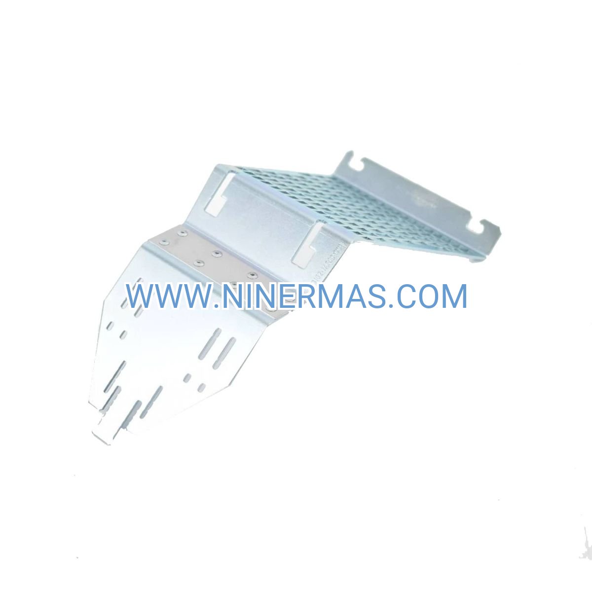
Siemens 6SL3130-7TE28-0AA3 SINAMICS S120 Smart Line Module (Industrial-Grade Regenerative Power Supply System)
The Siemens 6SL3130-7TE28-0AA3 SINAMICS S120 Smart Line Module is an advanced industrial power supply component designed for high-performance drive systems, utilizing active line module technology with integrated regenerative energy recovery capabilities to achieve intelligent power management and grid-side harmonic suppression. Through precise voltage and current control algorithms, this module ensures stable DC bus voltage while feeding braking energy back to the grid, significantly reducing overall system energy consumption.
Engineered for demanding industrial automation environments including manufacturing plants, material handling systems, process control applications, and heavy-duty machinery operations, this module addresses critical challenges such as energy waste during motor braking, power quality degradation, harmonic pollution, and excessive heat generation in traditional resistive braking systems. It provides reliable solutions for applications requiring frequent acceleration/deceleration cycles and regenerative operation modes.
Featuring standardized design with flexible configuration options, the 6SL3130-7TE28-0AA3 offers exceptional energy efficiency, superior grid compatibility, simplified maintenance procedures, and seamless integration with existing SINAMICS S120 drive platforms. Ideal for design engineers, system integrators, automation contractors, and end-user facilities seeking to optimize drive system performance. Contact our application engineers for customized selection guidance, technical specifications, and competitive quotations.
Core Functions & Technical Advantages
- Active Regenerative Energy Recovery
Employs IGBT-based active front-end topology with bidirectional power flow capability, capturing kinetic energy during motor deceleration and regenerating it back to the supply grid with efficiency exceeding 97%, eliminating the need for costly braking resistors and reducing thermal management requirements. - Significant Energy Savings Performance
Compared to conventional diode rectifier systems, achieves energy consumption reduction of 20-35% in typical duty cycles with frequent braking operations, delivering rapid ROI for continuous-operation industrial facilities and contributing to corporate sustainability objectives. - Superior Power Quality & Grid Compliance
Integrated active harmonic filtering maintains total harmonic distortion (THD) below 5% across full load range, ensuring compliance with IEEE 519 and IEC 61000 standards while improving power factor to >0.95, reducing utility penalties and protecting sensitive equipment. - Comprehensive Protection Architecture
Incorporates multi-layer protection mechanisms including overcurrent, overvoltage, undervoltage, phase loss detection, DC bus overvoltage, thermal overload monitoring, and ground fault protection, minimizing unplanned downtime and extending equipment service life. - Intelligent Monitoring & Diagnostics
Features integrated diagnostics with real-time parameter monitoring via PROFINET/PROFIBUS interfaces, supporting predictive maintenance strategies through continuous tracking of operating conditions, fault history logging, and alarm notification with detailed event timestamps. - Flexible System Scalability
Modular architecture allows parallel operation of multiple units for higher power requirements, supports distributed drive configurations, and enables seamless expansion of existing installations without major system redesign or extended commissioning periods.
Typical Application Scenarios
This Smart Line Module is specifically engineered for industrial environments demanding high power quality, energy efficiency, and operational reliability, particularly in:
- Metal Processing & Rolling Mills
Handles high-inertia loads in rolling stands, coilers, and uncoilers where frequent reversing operations generate substantial regenerative energy. Recovers braking power during strip deceleration, reduces peak demand charges, and maintains precise tension control throughout production cycles. - Material Handling & Logistics Systems
Powers conveyor systems, automated storage/retrieval systems (AS/RS), overhead cranes, and elevators in distribution centers and manufacturing facilities. Captures gravitational potential energy during lowering operations and provides smooth acceleration profiles for delicate cargo handling. - Process Industries & Continuous Production
Supports centrifuges, extruders, mixers, and pumping systems in chemical, pharmaceutical, food & beverage, and pulp & paper industries. Ensures stable process conditions through precise speed regulation while recovering energy from load variations and batch cycle transitions. - Test Benches & Dynamometer Applications
Ideal for motor testing facilities, vehicle dynamometers, and R&D laboratories requiring four-quadrant operation with accurate torque control. Regenerates absorbed mechanical power back to facility grid, dramatically reducing cooling infrastructure requirements and operating costs. - Renewable Energy & Hybrid Systems
Integrates with wind turbine pitch control systems, solar tracking mechanisms, and energy storage applications requiring bidirectional power conversion. Provides grid-friendly operation with configurable ramp rates and voltage support capabilities.
Technical Parameters & Selection Guidelines
To facilitate engineering design and equipment selection, we provide comprehensive technical specifications for the 6SL3130-7TE28-0AA3 model. Custom configurations are available to meet specific project requirements.
| Parameter | Specification |
| Model Number | 6SL3130-7TE28-0AA3 |
| Rated Power Output | 28 kW (continuous duty S1) |
| Input Voltage Range | 3-phase 380-480V AC ±10%, 50/60 Hz |
| DC Bus Voltage | 510-720V DC (nominal 600V) |
| Rated Input Current | Approximately 42A @ 400V AC |
| Power Factor | >0.95 (across full load range) |
| Total Harmonic Distortion | <5% THD (compliant with IEEE 519) |
| Regenerative Efficiency | >97% (energy recovery to grid) |
| Cooling Method | Forced air cooling (integrated fans) |
| Protection Rating | IP20 (standard enclosure) |
| Operating Temperature | 0°C to +40°C (derate above 40°C) |
| Storage Temperature | -25°C to +55°C |
| Relative Humidity | 5% to 95% (non-condensing) |
| Altitude Rating | Up to 1000m without derating |
| Communication Interfaces | PROFINET, PROFIBUS DP, USS, Modbus RTU |
| Compliance Standards | CE, UL, cUL, IEC 61800-5-1, IEC 61000 |
| Dimensions (H×W×D) | Approximately 275mm × 200mm × 235mm |
| Mounting Orientation | Vertical wall-mount or cabinet installation |
Selection Recommendations: When specifying this module, consider the following critical parameters: total connected motor power (including overload margins), supply voltage characteristics and stability, DC bus voltage requirements of connected motor modules, ambient temperature and ventilation conditions, required communication protocol compatibility, and available installation space including clearance for airflow. For complex multi-axis systems or applications with special requirements (harsh environments, extended temperature ranges, higher IP ratings), consult with our application engineering team who can provide detailed load analysis, thermal calculations, and customized cabinet layout drawings.
Advanced Integration Capabilities
- Multi-Drive Common DC Bus Configuration
Supports shared DC bus topology allowing multiple motor modules to exchange energy directly through common DC link, maximizing regenerative energy utilization in coordinated multi-axis applications such as printing presses, packaging machines, and textile equipment. - Industrial Network Integration
Native PROFINET and PROFIBUS connectivity enables seamless integration with Siemens SIMATIC controllers (S7-1200/1500, ET200 series), third-party PLCs, and SCADA systems. Supports cyclic data exchange for real-time control and acyclic services for parameter management and diagnostics. - Safety Function Integration
Compatible with SINAMICS Safety Integrated functions including Safe Torque Off (STO), Safe Stop 1 (SS1), and Safely-Limited Speed (SLS) when combined with appropriate motor modules and safety controllers, meeting SIL 2/PLd requirements per IEC 61508 and ISO 13849. - Energy Management & Monitoring
Provides detailed energy consumption data including active power, reactive power, power factor, and cumulative energy totals accessible via communication interfaces or optional operator panels, facilitating ISO 50001 energy management compliance and cost allocation.
Delivery, Service & Quality Assurance
Lead Time: Standard catalog items typically ship within 3-5 business days from regional distribution centers. Custom-configured systems or large quantity orders require 2-4 weeks depending on specifications and current production schedules.
Warranty Coverage: All units include comprehensive 12-month manufacturer warranty covering defects in materials and workmanship under normal operating conditions. Extended warranty programs and service contracts available upon request.
Technical Support: Complimentary pre-sales application engineering assistance including system sizing, configuration selection, and compatibility verification. Post-installation support includes remote diagnostics, parameter optimization guidance, and troubleshooting assistance via phone, email, or online portal.
Documentation Package: Each module ships with complete technical documentation including installation manual, quick start guide, detailed parameter reference, electrical connection diagrams, dimensional drawings (DXF/PDF formats), and safety instructions in multiple languages. EPLAN macros and 3D CAD models (STEP format) available for download.
Commissioning Services: Optional on-site startup and commissioning services available through our certified service partner network, including parameter configuration, system testing, operator training, and performance validation documentation.
Frequently Asked Questions (FAQ)
Q: How does the SINAMICS S120 Smart Line Module integrate with existing motor drive systems?
A: The 6SL3130-7TE28-0AA3 connects to the AC supply input and provides regulated DC bus voltage to one or more SINAMICS S120 motor modules via DC bus bars or cables. Integration requires matching DC bus voltage ratings (typically 600V class), proper sizing based on total motor power, and configuration of communication parameters. The module auto-detects supply voltage and can be commissioned using STARTER or SINAMICS Startdrive software tools. Existing installations can be retrofitted by replacing diode rectifier units with this active line module.
Q: What is the maximum number of motor modules that can be powered by one Smart Line Module?
A: A single 28kW Smart Line Module can supply multiple motor modules provided the sum of their continuous power ratings does not exceed 28kW, accounting for simultaneous operation and duty cycle characteristics. In common DC bus configurations with regenerative loads, the line module capacity can be optimized based on the net power flow rather than simple addition of motor ratings. For precise sizing in multi-axis applications, load profile analysis considering acceleration/deceleration patterns and regenerative energy distribution is recommended.
Q: What level of energy savings can be realistically achieved, and what factors influence this?
A: Energy savings typically range from 20% to 35% compared to conventional diode rectifier systems with braking resistors, with actual results depending on application duty cycle characteristics. Maximum savings occur in applications with frequent braking cycles (elevators, cranes, test stands) where regenerative energy represents a significant portion of total energy flow. Continuous pumping or fan applications with minimal braking see lower but still meaningful savings (10-15%) through improved power factor and reduced harmonic losses. Detailed energy audits can be performed using application-specific load profiles.
Q: What are the environmental installation requirements and protection class specifications?
A: The standard module features IP20 protection rating suitable for installation within enclosed control cabinets or electrical rooms with controlled environments. Ambient operating temperature range is 0°C to +40°C with linear derating required above 40°C (reduce by 2.5% per °C up to 50°C maximum). Installation location must provide adequate ventilation with minimum clearances: 100mm above and below for airflow, 50mm on sides. For harsh industrial environments (dust, moisture, corrosive atmospheres), specify IP54 cabinet enclosures with appropriate filtration, climate control, and corrosion-resistant coatings.
Q: Does the module support remote monitoring, data acquisition, and which industrial protocols are compatible?
A: Yes, comprehensive remote monitoring is supported through multiple industrial communication protocols including PROFINET (IRT capable), PROFIBUS DP (V2), USS serial protocol, and Modbus RTU. Real-time data accessible includes DC bus voltage, input current, active/reactive power, temperature, fault status, and diagnostic counters. Integration with SCADA systems, cloud-based monitoring platforms, and mobile applications is achievable through gateway devices or direct Ethernet connectivity. OPC UA server functionality available via SIMATIC S7 controller integration for Industry 4.0 applications.
Q: Can this module operate in standalone mode without a PLC, and what control options are available?
A: While the Smart Line Module can operate autonomously providing regulated DC bus voltage, practical drive system control requires coordination with motor modules which typically interface with automation controllers. Basic operator control panels (BOP-2, IOP) can be connected for manual parameter adjustment and status monitoring without PLC integration. For simple single-motor applications, the motor module's built-in technology functions (V/f control, vector control) can operate with minimal external control using digital inputs and analog setpoints.
Request Technical Consultation & Custom Solutions
To receive detailed application engineering support, customized system configuration recommendations, competitive project quotations, or technical clarification, please provide the following information to our specialist team:
- Project name and application description
- Industry sector and specific process requirements
- Total connected motor power and number of axes
- Duty cycle characteristics (continuous, intermittent, positioning)
- Supply voltage specifications and quality (voltage stability, existing harmonics)
- Ambient conditions (temperature range, altitude, environmental classification)
- Required communication protocols and automation platform
- Special requirements (extended warranty, commissioning support, training)
Our application engineers will respond within 24 business hours with personalized recommendations, technical feasibility assessment, and comprehensive quotation including all necessary components, accessories, and services.
© 2026 NINERMAS COMPANY LIMITED. All rights reserved.
Original Source: https://ninermas.com
Contact: sale@ninermas.com | +0086 187 5021 5667


Contact Info
-
Address:22 / F, South Wo Hang building, 148 Wing Lok Street, Sheung Wan, Western District, Hong Kong
-
Phone:+8618750215667
-
Email: