Siemens MICROMASTER 440 VFD 6SE6440-2UD41-1FB1 | 110kW 480V Industrial Drive | Energy-Efficient Motor Control
Description
Siemens MICROMASTER 440 Variable Frequency Drive (Industrial-Grade Energy-Efficient Control System)
The Siemens MICROMASTER 440 VFD (Model: 6SE6440-2UD41-1FB1) is an industrial-grade variable frequency drive engineered for precise motor speed control across demanding applications. Through advanced vector control technology and intelligent power management, this 110kW drive delivers exceptional energy efficiency, operational stability, and seamless integration with industrial automation systems.
Designed for manufacturing facilities, process industries, HVAC systems, and material handling operations, the MICROMASTER 440 addresses critical challenges including excessive energy consumption, motor wear from hard starts, process instability, and limited control flexibility. This drive is ideal for OEMs, system integrators, plant engineers, and maintenance teams seeking reliable, cost-effective motor control solutions.
Featuring standardized configuration with extensive customization options, the MICROMASTER 440 offers rapid commissioning, robust protection mechanisms, flexible communication interfaces, and proven reliability in harsh industrial environments. Contact our application engineers for tailored selection guidance, technical specifications, and competitive quotations.
Core Features & Performance Advantages
- Advanced Vector Control Technology
Implements sensorless vector control (VC) and V/f control modes, delivering precise speed regulation (±0.5% accuracy) and superior torque response across the entire speed range, ensuring optimal process control and product quality. - Significant Energy Savings
Achieves energy reduction of 20-40% compared to fixed-speed operation through optimized motor efficiency, reduced mechanical stress, and intelligent load matching—lowering operational costs in continuous-duty applications. - Comprehensive Motor Protection
Integrated protection suite includes overcurrent, overvoltage, undervoltage, overtemperature, ground fault, motor overload (I²t), and phase loss detection, minimizing downtime and extending equipment lifespan. - Flexible Communication Capabilities
Supports USS protocol via RS485 interface (standard), with optional PROFIBUS-DP, DeviceNet, and CANopen modules for seamless integration into PLC/DCS systems and Industry 4.0 architectures. - User-Friendly Operation Interface
Equipped with BOP-2 (Basic Operator Panel) featuring backlit LCD display, multi-language support (English/Chinese/German), real-time parameter monitoring, and intuitive navigation for simplified commissioning and troubleshooting. - Robust Industrial Design
IP20 enclosure (IP54 optional), conformal-coated PCBs for harsh environments, wide ambient temperature range (-10°C to +50°C), and proven EMC compliance ensure reliable operation in demanding industrial settings.
Typical Application Scenarios
The MICROMASTER 440 VFD excels in applications requiring precise speed control, energy efficiency, and operational reliability, particularly in:
- Pumping Systems & Fluid Handling
Controls centrifugal pumps in water treatment, chemical processing, and HVAC circulation systems, maintaining constant pressure or flow while reducing energy consumption and water hammer effects. - Fan & Ventilation Control
Regulates industrial fans, blowers, and exhaust systems in manufacturing facilities, cleanrooms, and commercial buildings, optimizing airflow based on demand and achieving substantial energy savings. - Conveyor & Material Handling
Drives belt conveyors, roller tables, and automated material transport systems in logistics, packaging, and production lines, providing smooth acceleration/deceleration and precise positioning control. - Compressor & Vacuum Systems
Manages rotary screw compressors and vacuum pumps in pneumatic systems, reducing compressed air costs through load-matching and soft-start capabilities that extend compressor service life. - Machine Tool & Processing Equipment
Powers spindle drives, feed mechanisms, and auxiliary equipment in metalworking, woodworking, and plastics processing, delivering consistent surface finish and dimensional accuracy.
Technical Specifications & Selection Guide
To facilitate engineering design and equipment selection, we provide comprehensive technical parameters for the 6SE6440-2UD41-1FB1 model, with custom configurations available for specific project requirements.
| Parameter | Specification |
|---|---|
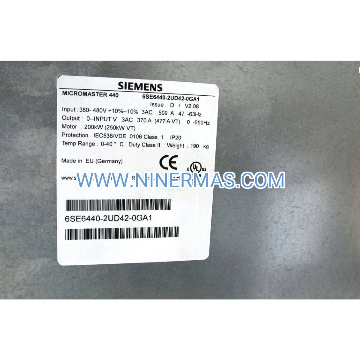
| Model Number | 6SE6440-2UD41-1FB1 |
| Power Rating | 110 kW (150 HP) |
| Input Voltage | 3-phase 380-480V AC ±10%, 50/60 Hz |
| Output Voltage | 0-Input Voltage, PWM modulated |
| Output Frequency | 0-650 Hz (configurable) |
| Control Method | Sensorless Vector Control / V/f Control |
| Overload Capacity | 150% for 60s, 200% for 3s |
| Protection Rating | IP20 (chassis), IP54 optional |
| Ambient Temperature | -10°C to +50°C (derate above 40°C) |
| Communication | RS485 (USS), optional PROFIBUS/DeviceNet |
| Dimensions (H×W×D) | Approx. 650×300×350 mm |
| Weight | Approx. 45 kg |
Selection Recommendations: When specifying a VFD, consider motor rated power and current, load characteristics (constant/variable torque), required speed range, environmental conditions (temperature, humidity, altitude), control interface requirements, and available installation space. For application-specific sizing, please provide motor nameplate data, duty cycle information, and process parameters—our engineers will recommend the optimal drive configuration and accessories.
Extended Functionality & Customization Options
- Advanced Control Modes: Eco mode for energy optimization, multi-motor control, flying start for spinning loads, DC braking, and skip frequency for resonance avoidance
- Communication Modules: PROFIBUS-DP, DeviceNet, CANopen, Modbus RTU for industrial network integration
- Operator Panels: AOP (Advanced Operator Panel) with graphical display and parameter cloning functionality
- Input/Output Expansion: Additional digital/analog I/O modules for complex control logic
- Braking Solutions: External braking resistors and chopper units for high-inertia loads and rapid deceleration
- EMC Filters: Class A/B EMC filters for compliance with stringent electromagnetic compatibility standards
Delivery, Service & Quality Assurance
Lead Time: Standard models typically ship within 3-5 business days from stock; custom-configured units require 10-15 business days depending on specifications.
Warranty Coverage: All MICROMASTER 440 drives include a comprehensive 12-month manufacturer warranty covering defects in materials and workmanship, with extended warranty options available.
Technical Support: Our application engineers provide pre-sales selection assistance, commissioning guidance, remote diagnostics, and on-site service (region-dependent). Comprehensive documentation including electrical schematics, parameter lists, quick start guides, and communication protocol manuals are supplied with each unit.
Quality Certifications: CE marked, UL/cUL listed, RoHS compliant, manufactured in accordance with ISO 9001 quality management systems.
Frequently Asked Questions (FAQ)
Q: How do I integrate the MICROMASTER 440 VFD with my existing motor system?
A: The drive connects between your power supply and motor via standard three-phase wiring. You'll need to verify motor voltage/current ratings match drive specifications, configure basic parameters (motor nameplate data, control mode, acceleration/deceleration times) via the BOP panel, and connect control signals (start/stop, speed reference) to digital/analog inputs. Detailed wiring diagrams and startup procedures are provided in the user manual.
Q: What is the maximum number of motors one MICROMASTER 440 can control?
A: Standard configuration controls one motor. For multi-motor applications, the drive can operate multiple motors of the same type simultaneously if the combined motor current does not exceed drive rating; however, individual motor protection requires external overload relays. For independent control of multiple motors, separate drives are recommended.
Q: What energy savings can I realistically expect, and what factors influence this?
A: Energy savings typically range from 20-40% in variable-torque applications (pumps, fans) where load varies with speed. Actual savings depend on load profile, operating duty cycle, system design, and baseline efficiency. Constant-torque loads (conveyors) see smaller savings (5-15%) primarily from soft-start and optimized acceleration. A detailed energy audit can provide project-specific estimates.
Q: What are the installation environment requirements and protection rating?
A: Standard IP20 enclosure requires installation in a clean, dry control cabinet with adequate ventilation (minimum clearances: 100mm top/bottom, 50mm sides). Ambient temperature range is -10°C to +50°C (derate 5% per °C above 40°C). For harsh environments, specify IP54 kit or install in NEMA-rated enclosure. Avoid direct sunlight, corrosive gases, conductive dust, and excessive vibration.
Q: Can the drive support remote monitoring and data acquisition? Which protocols are supported?
A: Yes, standard RS485 interface supports USS protocol for parameter access and monitoring. Optional communication modules enable PROFIBUS-DP, DeviceNet, CANopen, and Modbus RTU integration with SCADA systems, PLCs, and IoT gateways. Real-time data including speed, current, voltage, power, and fault status can be transmitted for predictive maintenance and process optimization.
Q: What protection features prevent motor and drive damage?
A: Comprehensive protection includes: electronic motor overload protection (thermal model), short circuit protection, ground fault detection, overvoltage/undervoltage lockout, DC bus overvoltage control, drive overtemperature shutdown, input phase loss detection, and output phase monitoring. Configurable fault responses (coast, ramp stop, continue) and automatic restart functions minimize process disruption.
Request Technical Support & Quotation
To receive detailed application engineering support, customized drive selection, or competitive pricing, please provide the following project information:
- Application description and industry sector
- Motor specifications (power, voltage, current, speed, service factor)
- Load characteristics (constant/variable torque, duty cycle, inertia)
- Control requirements (local/remote, communication protocol, I/O needs)
- Environmental conditions (temperature, altitude, enclosure type)
- Quantity required and delivery timeline
Our application engineers will respond within 24 hours with tailored recommendations, technical documentation, and project-specific quotations.
© 2026 NINERMAS COMPANY LIMITED. All rights reserved.
Original Source: https://ninermas.com
Contact: sale@ninermas.com | +0086 187 5021 5667


Contact Info
-
Address:22 / F, South Wo Hang building, 148 Wing Lok Street, Sheung Wan, Western District, Hong Kong
-
Phone:+8618750215667
-
Email: