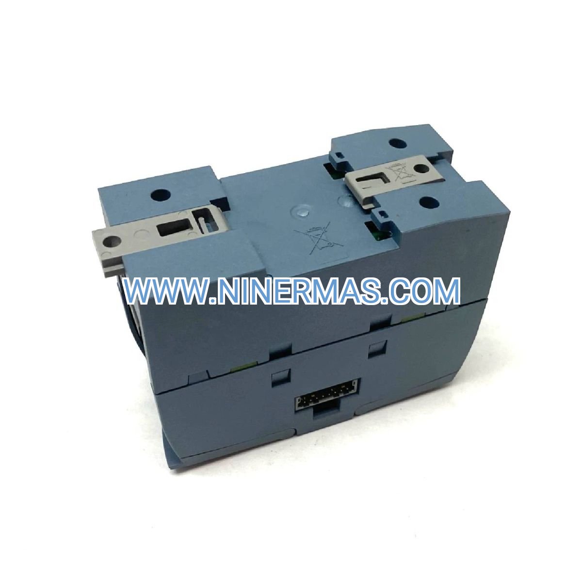
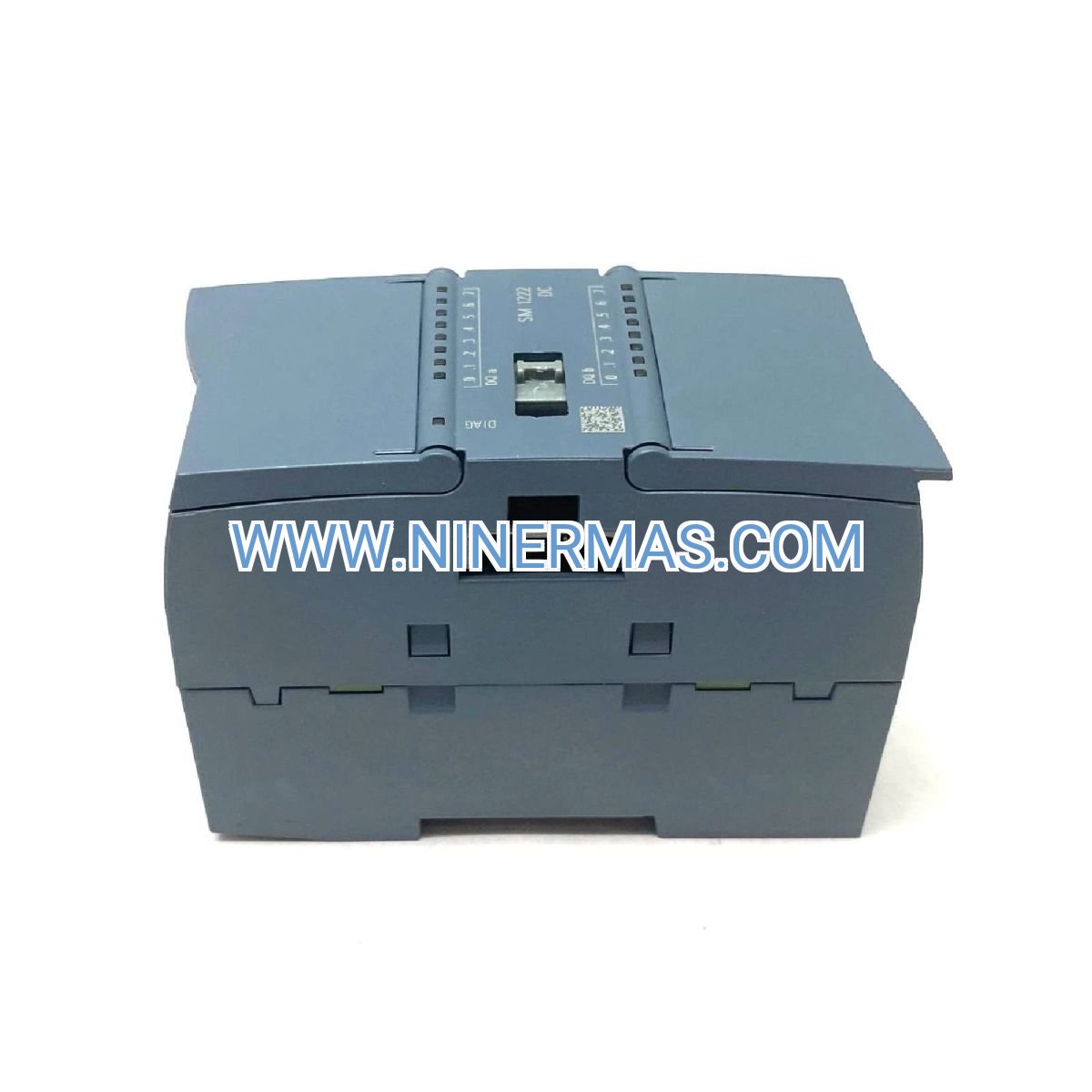
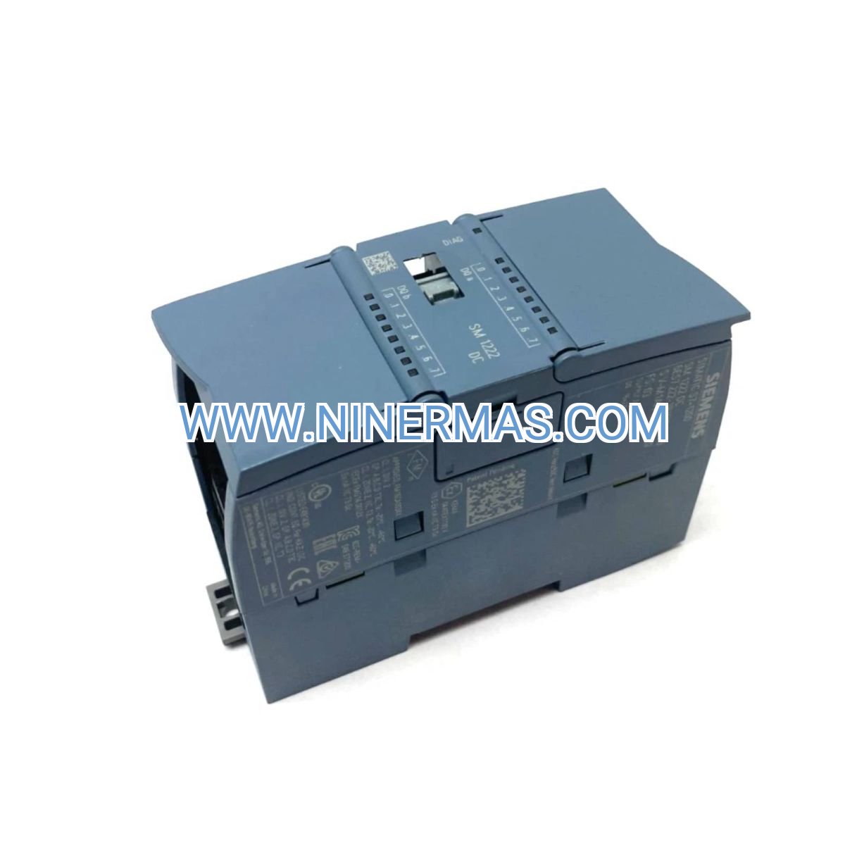
Siemens 6ES7222-1BF32-0XB0 | SM 1222 Digital Output Module 8DO 24VDC | S7-1200 PLC I/O
Description
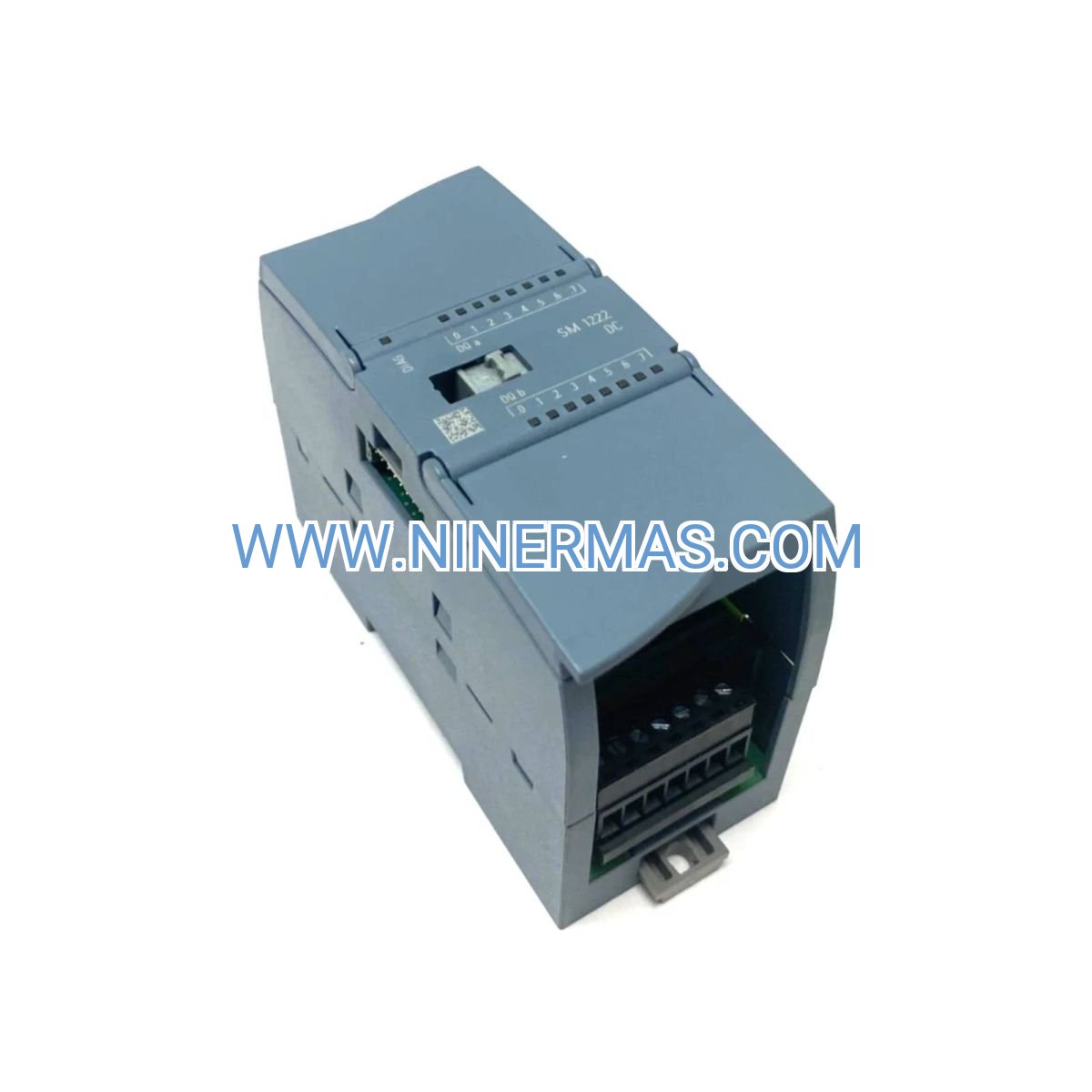
Siemens SM 1222 Digital Output Module (Industrial-Grade 24VDC Control Solution)
The Siemens 6ES7222-1BF32-0XB0 SM 1222 is a high-performance digital output module designed for SIMATIC S7-1200 PLC systems. Through precise 24VDC switching control and robust industrial-grade construction, it delivers reliable discrete output signals for actuators, solenoids, relays, and indicator lights in automated production environments.
Ideal for manufacturing automation, process control, and machine building applications where dependable digital output control is critical. This module addresses common challenges including signal interference, wiring complexity, insufficient output channels, and compatibility issues with legacy control systems.
Featuring standardized design with flexible configuration options, the SM 1222 offers fast response time, comprehensive diagnostics, hot-swappable capability, and seamless integration with TIA Portal. Suitable for system integrators, OEM machine builders, plant engineers, and maintenance teams. Contact our automation specialists for application guidance and technical specifications.
Core Features & Advantages
- 8-Channel Digital Output
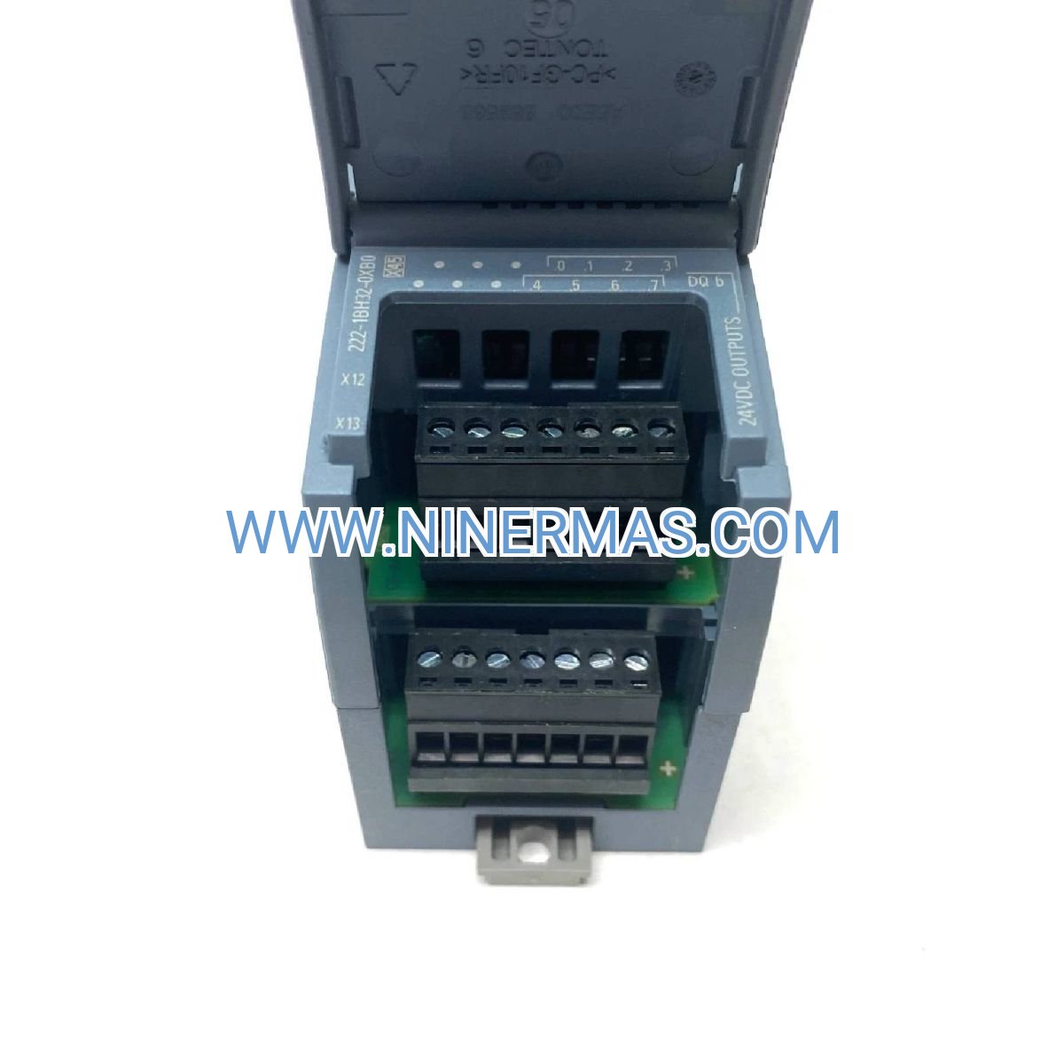
Provides eight independent 24VDC output channels with 0.5A per channel capacity, enabling simultaneous control of multiple field devices while reducing cabinet space and wiring costs. - Robust Industrial Design
Built to withstand harsh factory environments with IP20 protection, wide operating temperature range (-25°C to +60°C), and immunity to electromagnetic interference per IEC 61000 standards. - Plug-and-Play Integration
Seamlessly connects to S7-1200 CPU via high-speed backplane bus, with automatic hardware detection in TIA Portal, eliminating complex configuration and reducing commissioning time by up to 40%. - Comprehensive Diagnostics
Features channel-level fault detection including short-circuit protection, overload monitoring, and supply voltage supervision, with real-time status indication via LED and PLC diagnostics buffer. - Flexible System Expansion
Supports hot-swapping during operation (with CPU support), DIN rail mounting for easy installation, and cascading up to 8 signal modules per CPU for scalable I/O architecture. - Cost-Effective Operation
Low power consumption design (typical 1W), minimal maintenance requirements, and long service life reduce total cost of ownership for continuous industrial applications.
Typical Application Scenarios
This module excels in applications requiring reliable discrete output control with high availability and diagnostic capability:
- Manufacturing Assembly Lines
Controls pneumatic actuators, conveyor motors, and part ejectors in automotive, electronics, and packaging production lines where cycle time and uptime are critical. - Process Control Systems
Operates solenoid valves, pump starters, and alarm indicators in chemical processing, water treatment, and food & beverage facilities requiring precise sequencing and safety interlocks. - Machine Building & OEM Equipment
Provides standardized output interface for CNC machines, injection molding equipment, and material handling systems, simplifying machine design and global deployment. - Building Automation & HVAC
Manages damper actuators, fan contactors, and status lights in commercial HVAC systems, cleanrooms, and energy management applications. - Infrastructure & Utilities
Controls gate operators, pump stations, and remote terminal units in water distribution, wastewater treatment, and municipal infrastructure networks.
Technical Specifications & Selection Guide
To ensure optimal performance and compatibility, the SM 1222 module offers the following technical characteristics:
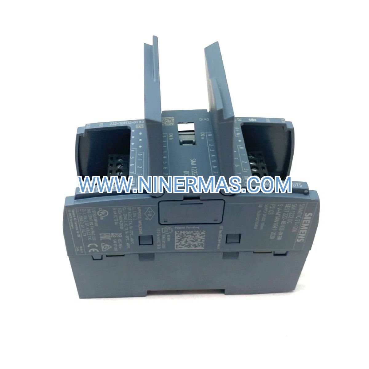
| Model Number | 6ES7222-1BF32-0XB0 |
| Output Type | Digital Output (DO), Transistor (sourcing) |
| Number of Channels | 8 channels |
| Output Voltage | 24VDC nominal (20.4-28.8VDC range) |
| Output Current | 0.5A per channel, 4A total (per group) |
| Electrical Isolation | 500VAC between channels and backplane bus |
| Response Time | ≤ 100μs (typical) |
| Protection Class | IP20 (DIN rail mounted) |
| Operating Temperature | -25°C to +60°C (horizontal mounting) |
| Dimensions (W×H×D) | 45mm × 100mm × 75mm |
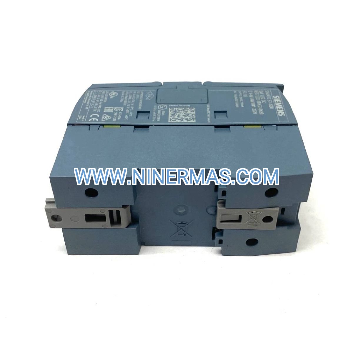
| Mounting | DIN rail (35mm standard rail) |
| Diagnostics | Channel status LED, PLC-accessible diagnostics |
| Certifications | CE, UL, cULus, ATEX (Zone 2), IECEx |
Selection Recommendations: When specifying this module, consider total output current requirements (ensure sum of simultaneous loads does not exceed group limits), load type (inductive loads may require external suppression), wiring distance (voltage drop considerations for long cable runs), and environmental conditions (temperature derating for vertical mounting or enclosed cabinets). For custom I/O configurations or multi-module systems, consult with our application engineers who can recommend optimal CPU and power supply sizing.
Advanced Configuration Options
- TIA Portal Integration: Full support for STEP 7 Basic/Professional V13 and later, with pre-configured function blocks for common output patterns (pulse generation, PWM, sequential control)
- Diagnostics & Monitoring: Configurable diagnostic interrupts, channel-specific error logging, and integration with SCADA/HMI systems via PROFINET or Modbus TCP
- Safety Considerations: Can be used in safety-related applications up to SIL 2 / PLd when combined with certified S7-1200 safety CPUs and proper system design
- Spare Parts Strategy: Hot-swap capability enables rapid replacement without system shutdown; recommended to stock spares for critical applications
Delivery, Service & Quality Assurance
Lead Time: Standard factory-sealed units typically ship within 1-3 business days from stock; custom-configured systems or bulk orders may require 5-10 business days.
Warranty: All modules include a comprehensive 12-month manufacturer warranty covering defects in materials and workmanship, with optional extended service agreements available.
Technical Support: Our certified Siemens automation specialists provide pre-sales application consulting, post-sales commissioning assistance, and remote troubleshooting support (availability varies by region).
Documentation Package: Each module ships with complete technical documentation including datasheet, wiring diagrams, TIA Portal hardware catalog entry, and quick-start installation guide in multiple languages.
Quality Standards: Manufactured in Siemens certified facilities under ISO 9001 quality management systems, with full traceability and compliance to international industrial automation standards.
Frequently Asked Questions (FAQ)
Q: How do I connect the SM 1222 digital output module to my existing S7-1200 PLC system?
A: The module connects directly to the right side of the S7-1200 CPU or another signal module via the built-in bus connector. Simply slide the module onto the DIN rail, push firmly against the adjacent module until the connector engages, and secure with the locking mechanism. The CPU will automatically detect the module upon power-up. External 24VDC power supply must be connected to the module's power terminals (refer to wiring diagram for proper polarity).
Q: What is the maximum number of SM 1222 modules I can connect to a single S7-1200 CPU?
A: The S7-1200 CPU supports up to 8 signal modules total (combination of digital input, digital output, and analog modules). You can install multiple SM 1222 modules as long as the total count does not exceed 8 and the CPU's I/O point capacity is not exceeded. Consult the specific CPU model datasheet for exact I/O limits.
Q: What energy savings or efficiency benefits does this digital output module provide?
A: The SM 1222 features low-power transistor outputs consuming approximately 1W during operation, significantly less than traditional relay-based output modules. The solid-state design eliminates mechanical wear, reducing maintenance costs by up to 60% compared to electromechanical alternatives. Precise switching control also minimizes energy waste in connected actuators and solenoid valves.
Q: What are the environmental and installation requirements for this module?
A: The module is rated IP20 for installation in enclosed control cabinets with adequate ventilation. Operating temperature range is -25°C to +60°C (horizontal mounting; derate to +55°C for vertical mounting). Ensure ambient conditions remain within specifications and provide minimum 25mm clearance above and below the module for airflow. Avoid installation near high-voltage switchgear or sources of electromagnetic interference.
Q: Can I monitor and diagnose output channel status remotely? What protocols are supported?
A: Yes, all channel status and diagnostic information is accessible via the S7-1200 CPU's communication interfaces. The CPU supports PROFINET, Modbus TCP, and S7 communication protocols, enabling integration with SCADA systems, HMI panels, and cloud-based monitoring platforms. Diagnostic data includes individual channel status, short-circuit detection, and power supply monitoring. TIA Portal provides built-in diagnostic views for local troubleshooting.
Q: Is this module suitable for controlling inductive loads like solenoid valves and motor contactors?
A: Yes, the transistor outputs can switch inductive loads, but external suppression (flyback diodes or varistors) is recommended to protect the output transistors from voltage spikes during load de-energization. Ensure the inductive load current does not exceed 0.5A per channel and follow proper wiring practices to minimize electrical noise. For highly inductive loads, consider using external relay interfaces.
Get Expert Selection Support
To ensure optimal module selection and system design for your specific application, please provide the following information to our automation engineering team:
- Project name and application type (manufacturing, process control, OEM machine, etc.)
- Number and type of output devices to be controlled (solenoids, relays, indicators, etc.)
- Total output current requirements and load characteristics (resistive, inductive, lamp loads)
- Existing S7-1200 CPU model and current I/O configuration
- Environmental conditions (temperature range, enclosure type, hazardous area classification if applicable)
- Required certifications or compliance standards for your region/industry
Our engineers will provide personalized module recommendations, wiring diagrams, and technical specifications tailored to your project requirements.
© 2026 NINERMAS COMPANY LIMITED. All rights reserved. Original Source: https://ninermas.com Contact: sale@ninermas.com | +0086 187 5021 5667


Contact Info
-
Address:22 / F, South Wo Hang building, 148 Wing Lok Street, Sheung Wan, Western District, Hong Kong
-
Phone:+8618750215667
-
Email: