Original Industrial Spare Part
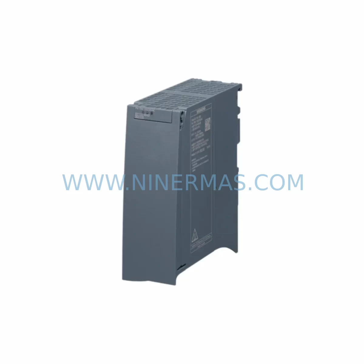
Siemens 6EP1332-4BA00 Retrofit Power Supply for Legacy Systems
Verify the part, confirm the platform family, and move straight into quotation with the right commercial details.
RFQ Ready
- SKU6EP1332-4BA00
- CategoryPLC & Industrial Automation Modules
- BrandSiemens
- SupportAvailability, lead time, condition, and shipping coordination
How Buyers Usually Use This Page
- Confirm the exact part number and platform family before sending the quote request.
- Use direct email when quantity, condition, and destination are already defined internally.
- Switch to the broader brand or category archive when you need alternates nearby.
Series Navigation
Move through the most common platform families behind this part.
Product RFQ
Send this part directly for quotation.
Include quantity, required condition, destination country, and target delivery timing. Current reference: Siemens 6EP1332-4BA00 Retrofit Power Supply for Legacy Systems with SKU 6EP1332-4BA00.
Siemens 6EP1332-4BA00 Retrofit Power Supply for Legacy Systems
The Siemens 6EP1332-4BA00 is a SITOP modular series 24 V DC stabilized power supply delivering 5 A output current, designed for DIN rail mounting in industrial control cabinets. As legacy Siemens automation platforms reach end-of-life, the 6EP1332-4BA00 has become a critical retrofit component for engineers tasked with sustaining production continuity without full system replacement. Its compact footprint, wide-range AC input (85–264 V AC), and robust short-circuit protection make it a direct drop-in candidate for aging SITOP and PS307 power supply positions across S7-300, S7-200, and equivalent third-party PLC racks. Whether you are restoring a failed power rail in a legacy control cabinet, upgrading an obsolete 24 V supply in a distributed I/O panel, or consolidating power architecture during a phased migration to a newer Siemens platform, the 6EP1332-4BA00 provides the electrical compatibility and physical form factor required to minimize engineering rework and reduce overall retrofit cost.
Upgrade Compatibility Table
| Parameter | Specification | Retrofit Notes |
|---|---|---|
| Input Voltage | 85–264 V AC / 110–300 V DC (wide range) | Compatible with single-phase industrial supply; no step-down transformer required in most legacy panels |
| Output Voltage | 24 V DC (adjustable 22.8–26.4 V) | Matches standard 24 V DC bus used by S7-300 I/O modules and field devices |
| Output Current | 5 A continuous | Verify total load of connected modules before replacement; upgrade to 6EP1334-3BA10 (10 A) if load exceeds 4.5 A |
| Mounting | DIN rail (35 mm TS 35) | Direct replacement on standard DIN rail; no bracket modification required |
| Dimensions (W×H×D) | 50 × 125 × 125 mm | Confirm available cabinet width; adjacent modules may require repositioning |
| Protection Class | IP20 | Suitable for enclosed control cabinet installation; not for open-air or wet environments |
| Communication Interface | None (standalone DC supply) | No bus connection required; compatible with all PROFIBUS and PROFINET backplane configurations |
| Replacement Compatibility | Siemens PS307 5A, SITOP smart 5A, equivalent 24 V/5 A DIN rail supplies | Terminal pitch and wiring layout are compatible; re-use existing cable ferrules where possible |
| Commissioning Requirement | Output voltage adjustment via trimmer | Set to 24.0 V DC before energizing connected PLC rack |
| Warranty | 12 Months | Covered from date of shipment; includes DOA replacement and functional verification report on request |
Retrofit Planning for Existing Automation Systems
Successful integration of the 6EP1332-4BA00 into an existing automation system begins with a thorough audit of the current power distribution architecture. In a typical S7-300 control cabinet, the power supply feeds the CPU rack — such as a 6ES7315-2AH14-0AB0 CPU 315-2 DP — along with digital input modules like the 6ES7321-1BL00-0AA0 (32-channel DI) and digital output modules such as the 6ES7322-1BL00-0AA0 (32-channel DO). Before removing the failed or obsolete supply, document the total current draw of all installed modules, including any communication processors such as the 6GK7343-1EX30-0XE0 CP343-1 Ethernet module, which adds approximately 0.16 A to the 24 V bus.
Terminal wiring should be photographed and labeled before disconnection. The 6EP1332-4BA00 uses standard screw terminals compatible with 0.5–6 mm² conductors; existing ferrule-terminated wiring from a PS307 or earlier SITOP supply can typically be re-used without re-crimping. If the cabinet uses a 6ES7390-1AE80-0AA0 DIN rail section with a 6ES7392-1AM00-0AA0 front connector arrangement, confirm that the new supply’s terminal block does not conflict with adjacent module connectors during insertion.
For systems where a 6AV2124-0GC01-0AX0 KTP700 Basic HMI panel is present, verify that the HMI’s 24 V supply input is either sourced from the same rail or from a dedicated secondary supply. Sharing a single 5 A output between the PLC rack and an HMI panel may exceed the rated load; in such cases, a second 6EP1332-4BA00 or a higher-capacity unit is recommended. PROFIBUS networks using 6ES7972-0BB12-0XA0 bus connectors are unaffected by the power supply swap, as PROFIBUS signal integrity is independent of the 24 V DC supply rail. However, after power restoration, confirm that all slave addresses are recognized by the master CPU before resuming automatic operation.
Where the retrofit involves migrating from an S7-200 or third-party PLC platform, a signal isolator or I/O conversion module may be required between legacy field wiring and the new I/O rack. Confirm module address assignments in the hardware configuration tool (STEP 7 or TIA Portal) match the physical slot positions before downloading the updated program to the CPU.
Downtime Control During System Migration
Minimizing unplanned downtime during a power supply replacement requires preparation before the maintenance window begins. Start by backing up the current CPU program using a SIMATIC memory card or PC adapter cable, ensuring the program logic, data blocks, and hardware configuration are preserved independently of the power supply state. If the system uses a 6ES7307-1EA01-0AA0 PS307 10 A supply in a multi-rack configuration, plan the replacement rack by rack to maintain partial production capability during the migration window.
During the physical swap, use a temporary 24 V DC bench supply connected to the output terminals to keep field devices and sensors energized while the main supply is removed. This approach preserves sensor states and prevents false alarms on safety relay circuits. After installing the 6EP1332-4BA00, adjust the output trimmer to 24.0 V DC under no-load conditions, then reconnect the load progressively — starting with the CPU rack, followed by I/O modules, and finally field devices — monitoring output voltage stability at each stage.
Once the system is fully energized, perform a structured commissioning check: verify all I/O module status LEDs, confirm PROFIBUS or PROFINET communication links are active, and execute a test cycle of the machine sequence before returning to automatic mode. Total replacement time for a single-rack S7-300 system is typically 45–90 minutes when pre-planned, with a functional verification report available on request for quality documentation purposes. All units supplied by NINERMAS carry a 12-month warranty from the date of shipment, covering manufacturing defects and early-life failures.
Retrofit Support FAQ
Q1: Is the 6EP1332-4BA00 a direct replacement for the Siemens PS307 5A (6ES7307-1BA01-0AA0)?
Yes. The 6EP1332-4BA00 SITOP modular 5 A and the PS307 5 A share the same 24 V DC / 5 A output rating and DIN rail mounting format. Terminal positions differ slightly; re-terminate wiring according to the 6EP1332-4BA00 datasheet. Output voltage should be verified and adjusted to 24.0 V DC before reconnecting the PLC rack.
Q2: What commissioning steps are required after installation?
Set output voltage to 24.0 V DC using the front trimmer under no-load conditions. Reconnect load progressively and verify output voltage remains within 22.8–26.4 V DC under full load. Confirm all PLC module status indicators are normal, re-establish communication links (PROFIBUS/PROFINET), and perform a supervised test cycle before returning the system to automatic operation.
Q3: How is compatibility with existing field wiring verified?
The 6EP1332-4BA00 accepts conductors from 0.5 to 6 mm² on its input and output terminals. Existing ferrule-terminated wiring from PS307 or earlier SITOP supplies is generally compatible. Verify conductor cross-section, terminal torque specification (0.8 Nm), and polarity labeling before energizing. For systems with 24 V DC field devices, confirm device voltage tolerance (typically ±10%) is met at the measured output.
Q4: What are the stock availability and warranty terms?
NINERMAS maintains in-stock inventory of the 6EP1332-4BA00 for immediate shipment. All units are covered by a 12-month warranty from the date of shipment, including DOA (dead-on-arrival) replacement. A functional test report confirming output voltage, ripple, and short-circuit protection performance is available on request prior to shipment. Contact sale@ninermas.com or call +0086 187 5021 5667 for current stock levels and lead times.
| Product Series | SITOP |
|---|---|
| Country of Origin | DE |
Catalog Continuation
More Siemens modules in the catalog.
Use the brand lane to compare nearby part numbers, platform-adjacent modules, and other inquiry-ready listings before sending your final RFQ.
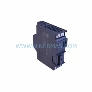
SKU: 6ES7341-1AH01-0AE0
Siemens 6ES7341-1AH01-0AE0 Retrofit-Compatible CP341 for Legacy Systems
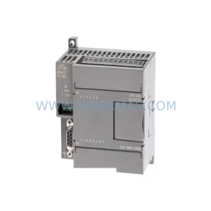
SKU: 6SL3352-3AG35-8AA0
Siemens 6SL3352-3AG35-8AA0 Service-Ready Spare Part for Industrial Maintenance
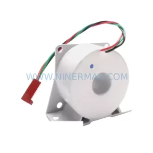
SKU: 6SY7000-0AA31
SIEMENS 6SY7000-0AA31 Retrofit-Compatible Rectifier Unit
Catalog Continuation
Alternative parts within PLC & Industrial Automation Modules.
Stay inside the same system family when you need substitutes, adjacent modules, or a broader shortlist for procurement review.
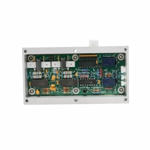
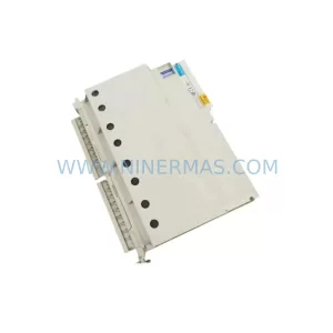
SKU: GIGA-F 0090-36221 0190-04562 H SK.CTD.200-0DEG F.D. 0040-95291
AMAT 0090-36221 Retrofit-Compatible TC Amp for Legacy Systems