Description
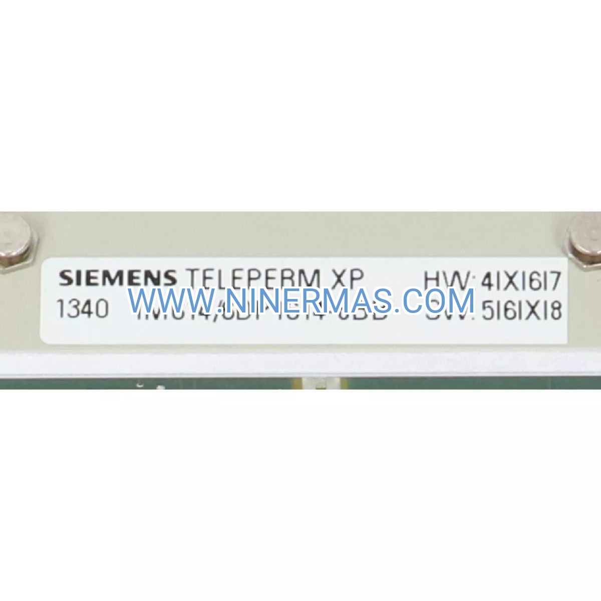
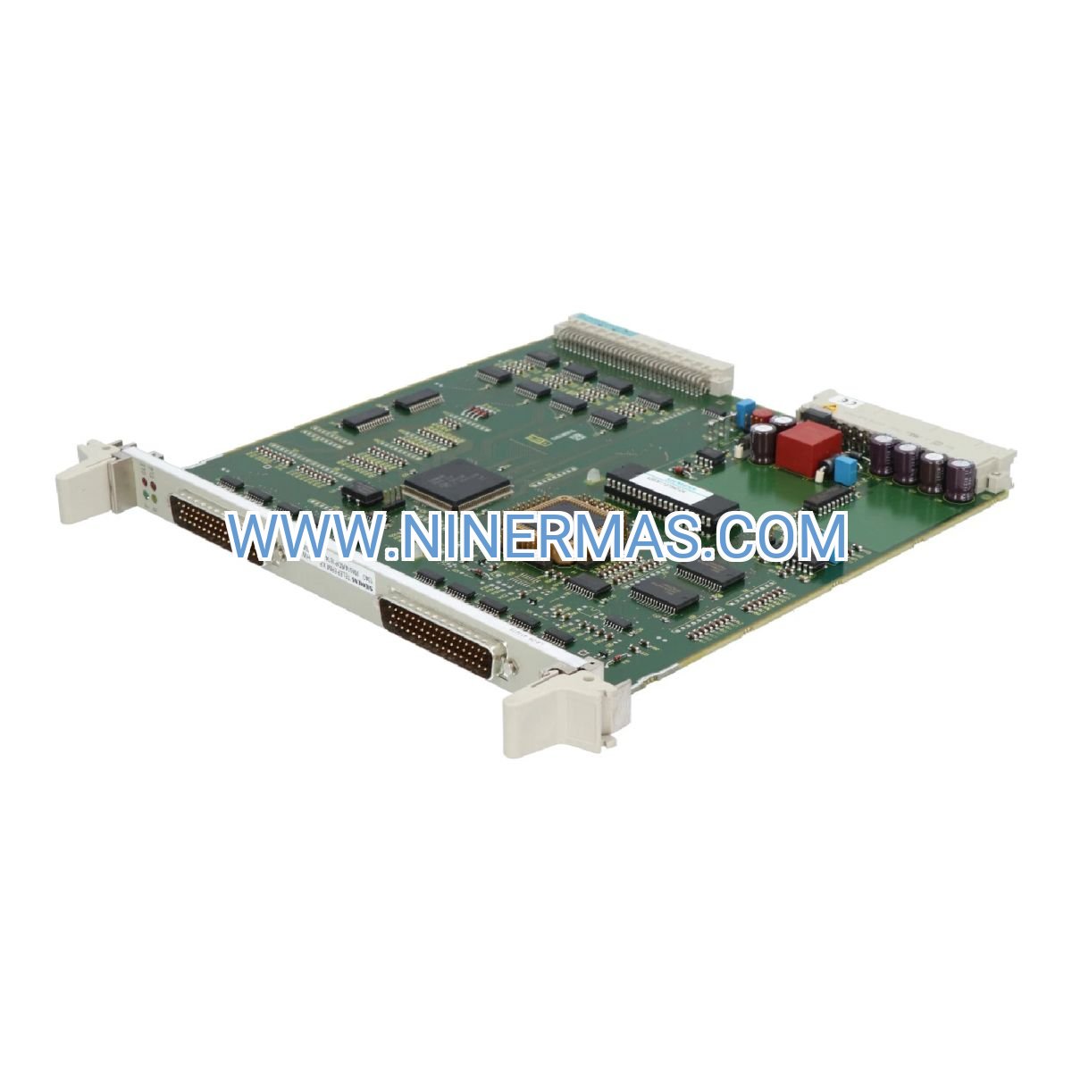
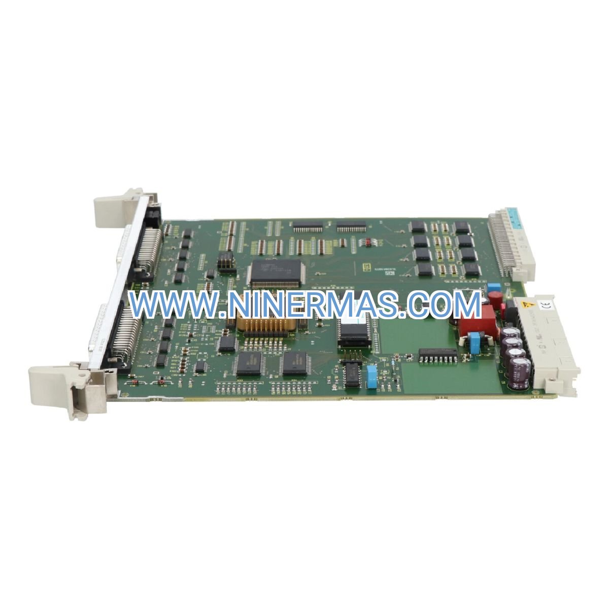
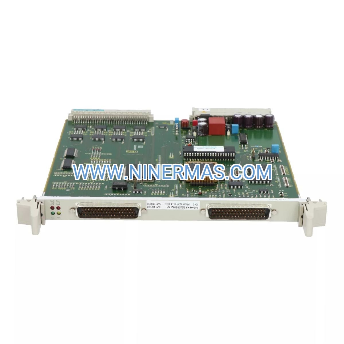
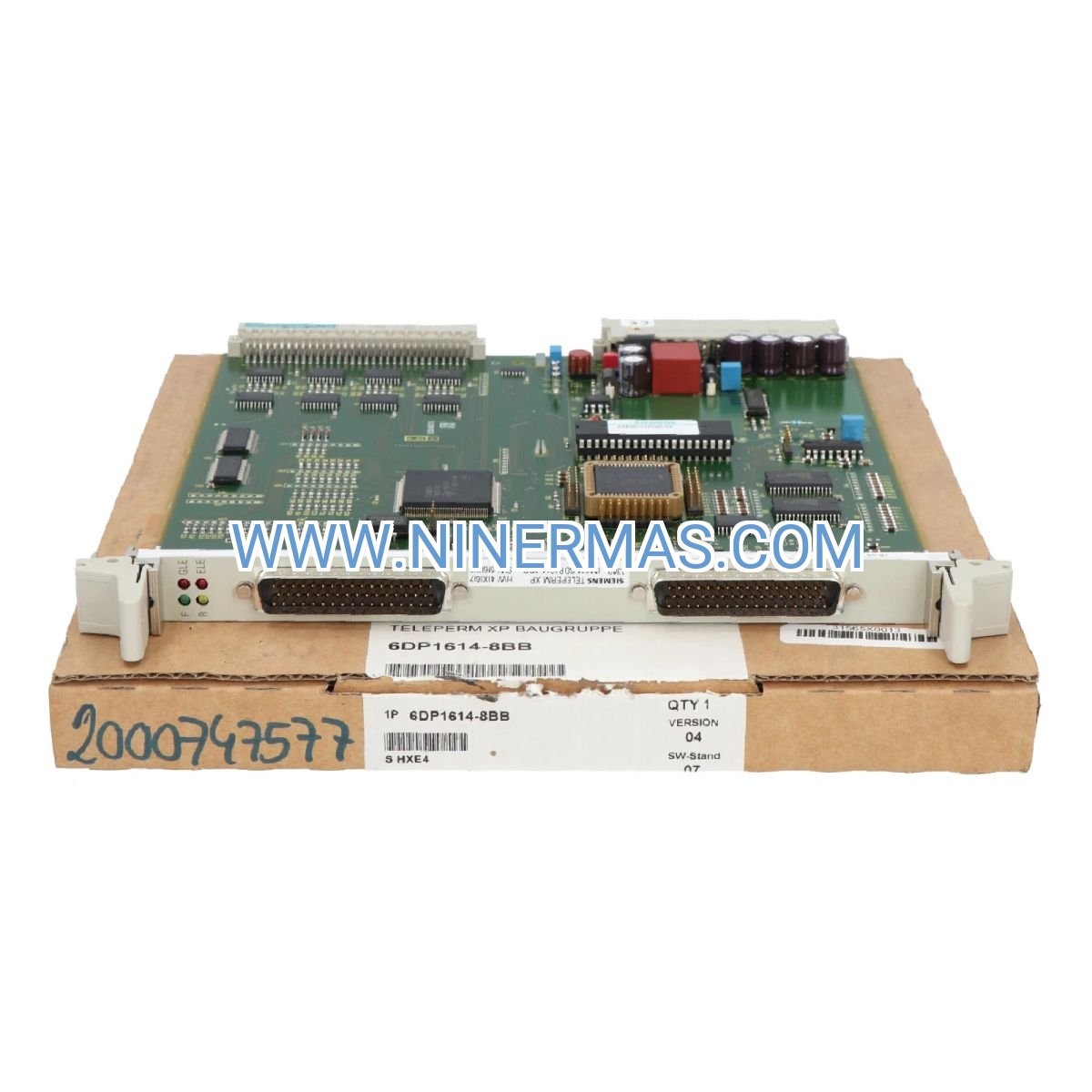
Siemens IM 614 Interface Module (Industrial-Grade Communication Hub)
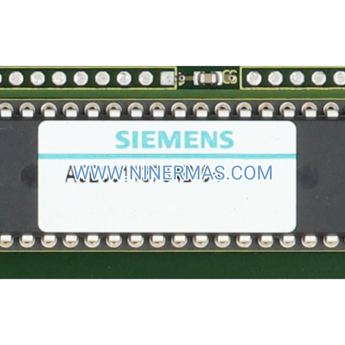
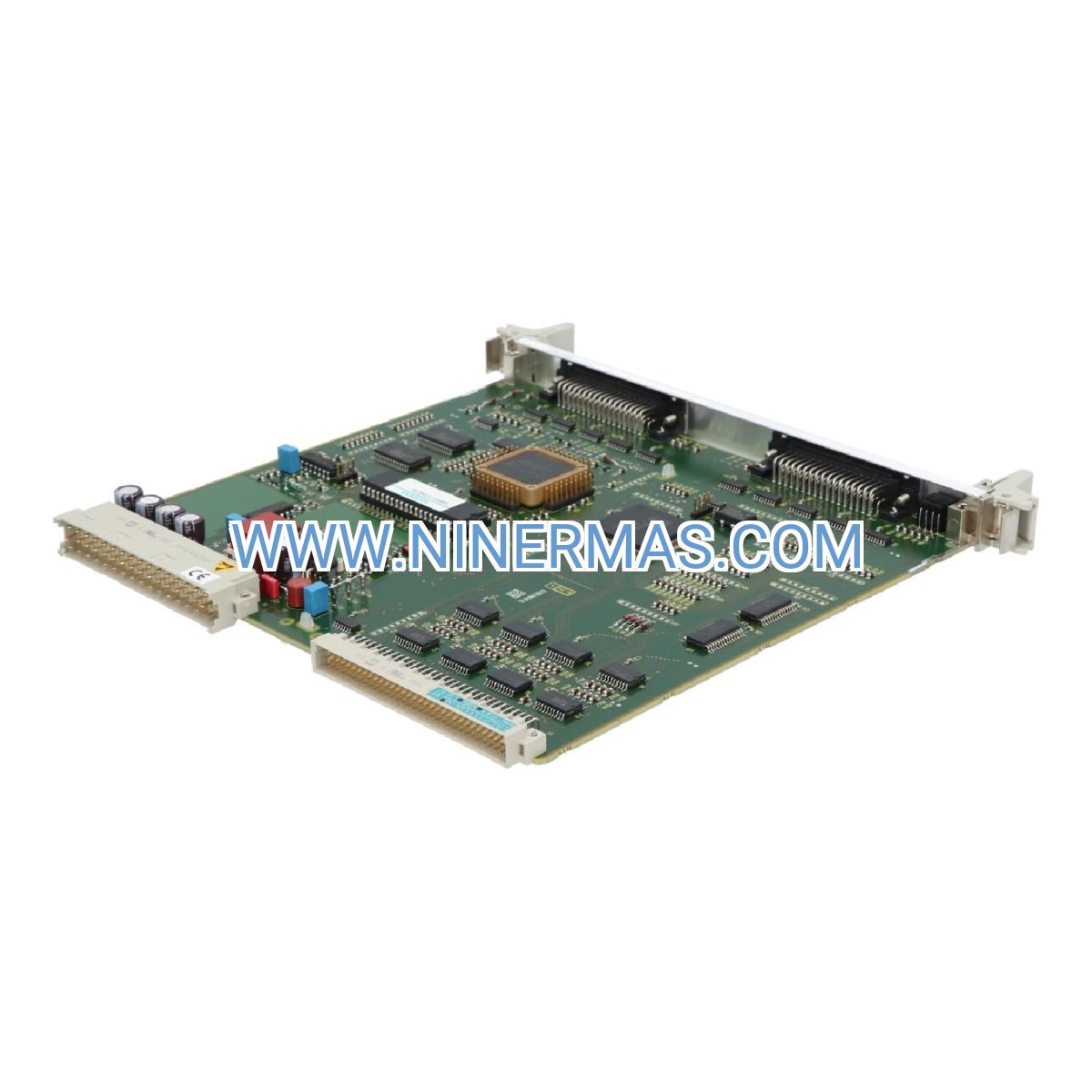
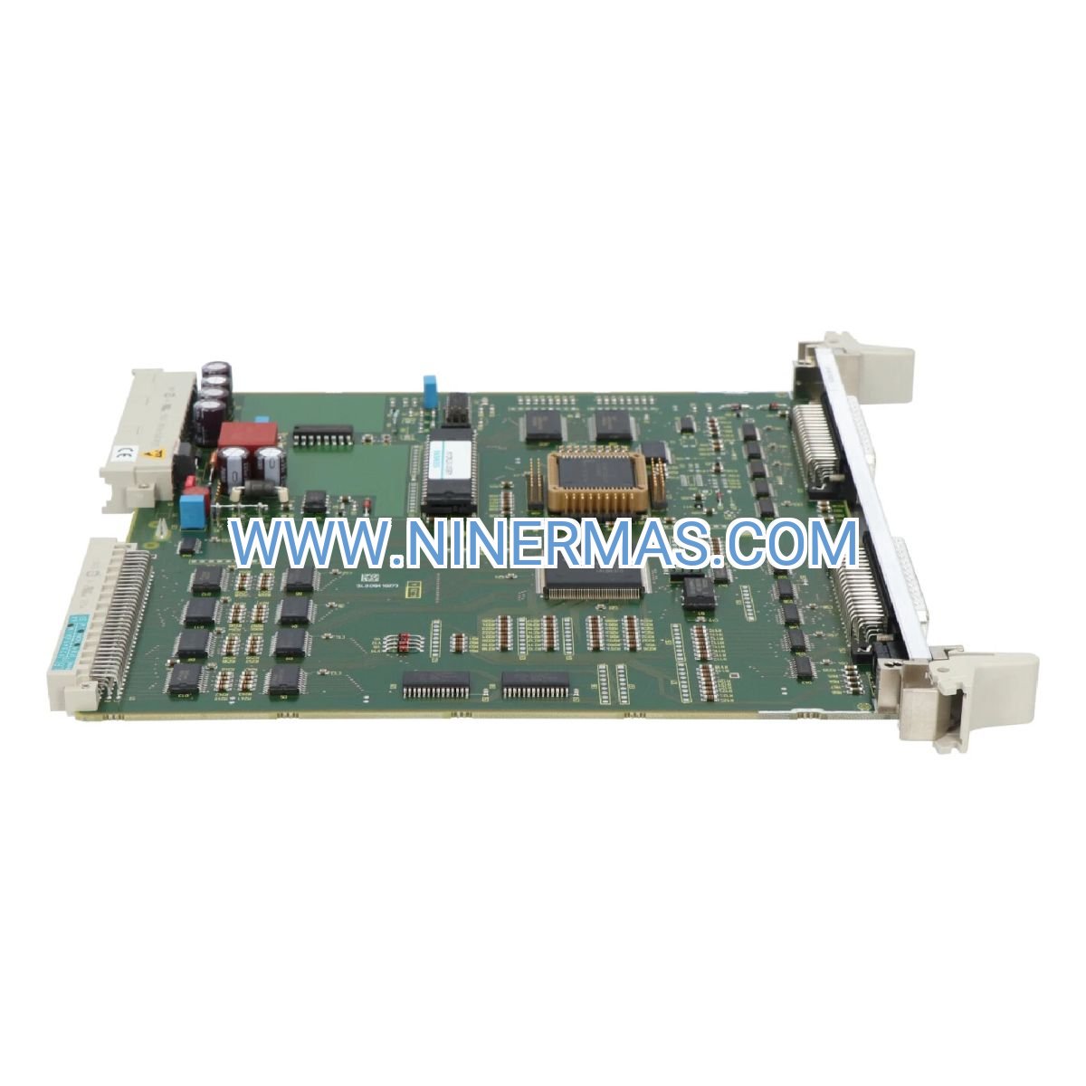
The Siemens 6DP1614-8BB represents a mission-critical communication gateway within TELEPERM XP distributed control architectures. Designed for continuous operation in demanding industrial settings, this interface module establishes reliable data pathways between central processors and field-level devices through the CS 275 bus protocol. Organizations operating legacy TELEPERM XP installations depend on the IM 614 to maintain system integrity while supporting incremental modernization strategies.
Process industries facing stringent uptime requirements benefit from the module's redundancy-ready design and deterministic communication cycles. Whether coordinating turbine control sequences in power generation facilities or synchronizing distributed I/O networks across chemical processing units, the IM 614 delivers the predictable performance that safety-critical applications demand. Its proven track record in harsh environments makes it the preferred choice for plant engineers managing long-lifecycle control systems.
With hot-swappable capability and comprehensive diagnostic features, maintenance teams can perform service operations without disrupting production workflows. The module's compatibility with standard TELEPERM XP engineering tools ensures seamless integration into existing control strategies, protecting capital investments while enabling future-ready connectivity options.
Core Capabilities & Business Value
✓ Deterministic CS 275 Bus Communication
Guarantees fixed-cycle data exchange with sub-millisecond jitter tolerance, essential for coordinating time-sensitive control loops across distributed process units. Eliminates communication-induced delays that could compromise product quality or safety margins.
✓ Redundancy-Enabled Architecture
Supports automatic failover configurations that maintain control continuity during primary controller faults. Reduces unplanned downtime costs by enabling seamless switchover without manual intervention or process interruption.
✓ Hot-Swap Serviceability
Allows module replacement during live operation, minimizing maintenance windows and preserving production schedules. Maintenance teams can address component issues without coordinating plant-wide shutdowns or losing historical data buffers.
→ Extended Temperature Range (0°C to +60°C)
Operates reliably in non-climate-controlled industrial environments, from outdoor substations to high-ambient manufacturing floors. Reduces auxiliary cooling requirements and associated energy costs compared to commercial-grade alternatives.
→ Integrated Diagnostic Indicators
Front-panel LEDs provide instant visibility into operational status, communication activity, and fault conditions. Accelerates troubleshooting workflows by enabling technicians to identify issues without connecting diagnostic equipment.
→ DIN Rail Mounting Compatibility
Installs directly into standard TELEPERM XP control cabinets using universal mounting hardware. Simplifies retrofit projects and spare parts management across multi-site installations with consistent mechanical interfaces.
Industry Applications & Problem-Solving
Power Generation & Utilities
Challenge: Coordinating turbine governor controls, excitation systems, and protection relays requires microsecond-level synchronization across geographically distributed equipment.
Solution: The IM 614 establishes deterministic communication links that maintain phase-locked coordination between generator control units and auxiliary systems, preventing grid instability events caused by timing discrepancies.
Chemical & Petrochemical Processing
Challenge: Batch reactors demand precise sequencing of valve actuators, temperature controllers, and material feed systems to maintain product specifications and safety margins.
Solution: By providing reliable data pathways between central batch controllers and field I/O modules, the IM 614 ensures recipe execution accuracy while enabling real-time adjustments based on in-process measurements.
Pulp & Paper Manufacturing
Challenge: Continuous web processes require synchronized speed control across multiple drive sections to prevent sheet breaks and maintain tension profiles.
Solution: The module's low-latency communication enables coordinated setpoint distribution to distributed drive controllers, maintaining cross-machine directional consistency within tolerance bands that prevent quality defects.
Water & Wastewater Treatment
Challenge: Treatment plants must coordinate pump stations, aeration systems, and chemical dosing equipment across campus-scale facilities while maintaining regulatory compliance.
Solution: IM 614 modules link remote pump houses and treatment stages to central SCADA systems, enabling operators to optimize energy consumption while meeting discharge permit requirements through coordinated process adjustments.
Legacy System Modernization
Challenge: Organizations with capital-intensive TELEPERM XP installations need connectivity to modern analytics platforms without replacing functional control hardware.
Solution: The IM 614 serves as a stable foundation for gateway implementations that bridge CS 275 networks to Ethernet-based SCADA systems, preserving existing control logic while enabling cloud connectivity for predictive maintenance applications.
Technical Parameters & Selection Criteria
| Parameter | Specification |
|---|---|
| Catalog Number | 6DP1614-8BB |
| Product Family | TELEPERM XP |
| Module Classification | Interface Module IM 614 |
| Communication Protocol | CS 275 Bus System |
| Maximum Bus Length | 1000 meters (shielded cable) |
| Operating Temperature | 0°C to +60°C |
| Storage Temperature | -40°C to +70°C |
| Enclosure Rating | IP20 |
| Mounting Method | DIN Rail (35mm standard) |
| Module Weight | 0.5 kg |
| Country of Origin | Germany |
| Redundancy Support | Yes (automatic failover) |
Selection Guidelines: Verify compatibility with your existing TELEPERM XP controller generation by cross-referencing system documentation. For installations requiring cable runs exceeding 500 meters, implement signal repeaters at recommended intervals. In redundant configurations, procure modules in matched pairs to ensure firmware consistency. Consult factory documentation for specific slot assignment requirements within your control cabinet layout.
Advanced Integration Features
Multi-Drop Network Topology
The CS 275 bus architecture supports up to 32 addressable nodes per segment, enabling cost-effective distribution of I/O capacity across process areas. This reduces point-to-point wiring complexity compared to star-configured systems while maintaining deterministic scan cycles.
Configuration Management
Module parameters are stored in non-volatile memory, eliminating the need for battery-backed retention. Configuration changes made through the TELEPERM XP engineering station are automatically synchronized across redundant module pairs, simplifying commissioning workflows.
Protocol Bridging Readiness
When paired with compatible gateway hardware, the IM 614 enables data exchange between TELEPERM XP networks and modern industrial Ethernet protocols (PROFINET, Modbus TCP). This facilitates phased migration strategies that preserve existing control logic while adding connectivity to MES and ERP systems.
Customization Options
For applications requiring specialized communication timing or extended environmental ratings, consult with our application engineering team. Custom firmware configurations and conformal coating treatments are available for projects with unique specifications.
Delivery Timeline & Service Commitments
Standard Lead Time: 3-5 business days for in-stock units (subject to verification)
Engineered Configurations: 4-6 weeks for custom firmware or extended testing requirements
Warranty Coverage: 12-month comprehensive warranty covering manufacturing defects and component failures
Technical Support: Application engineering assistance available throughout product lifecycle, including configuration guidance, troubleshooting support, and obsolescence management planning
Documentation Package: Each shipment includes installation manual, wiring diagrams, and configuration templates compatible with TELEPERM XP engineering tools
Frequently Asked Questions
What cable specifications are required for CS 275 bus connections?
Use shielded twisted-pair cable with characteristic impedance of 120 ohms and minimum 0.5mm² conductor cross-section. Maintain shield continuity through 360-degree clamp connections at both ends, with shield grounding at a single point to prevent ground loops.
Can the IM 614 interface module operate in SIL-rated safety applications?
The standard IM 614 is designed for process control applications. For safety-instrumented systems requiring SIL certification, consult Siemens safety system product lines specifically engineered for functional safety compliance.
How does the module handle communication errors or bus faults?
Built-in error detection algorithms monitor frame integrity and timing violations. Upon detecting persistent faults, the module activates diagnostic LEDs and generates alarm signals to the host controller. In redundant configurations, the system automatically switches to the backup communication path.
What is the typical power consumption of the IM 614 module?
The module draws approximately 5 watts from the TELEPERM XP backplane power supply under normal operating conditions. Verify that your cabinet power budget accommodates the total module count, including margin for inrush currents during system startup.
Is remote monitoring of module status possible?
Diagnostic data is accessible through the TELEPERM XP engineering interface, which can be networked for remote access. For integration with plant-wide asset management systems, implement OPC servers or similar middleware that exposes module health parameters to SCADA platforms.
What are the recommended spare parts stocking levels?
For critical process applications, maintain at least one spare module per 10 installed units. High-availability installations should stock pre-configured modules to minimize mean time to repair during unplanned failures.
Get Expert Guidance for Your Control System
Our application engineering team specializes in TELEPERM XP system integration and modernization projects. Whether you're expanding existing installations, troubleshooting communication issues, or planning migration strategies, we provide technical consultation tailored to your operational requirements.
Contact us today for:
- Compatibility verification with your specific controller generation
- Custom configuration assistance for complex network topologies
- Obsolescence management planning and lifecycle extension strategies
- Competitive quotations with volume pricing for multi-site deployments
Request a technical consultation or quotation →
© 2026 NINERMAS COMPANY LIMITED. All rights reserved.
Original Source: https://ninermas.com
Contact: sale@ninermas.com | +0086 187 5021 5667


Contact Info
-
Address:22 / F, South Wo Hang building, 148 Wing Lok Street, Sheung Wan, Western District, Hong Kong
-
Phone:+8618750215667
-
Email: