Original Industrial Spare Part
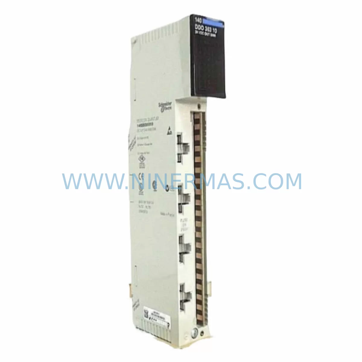
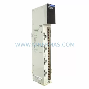
Schneider 140DDO35301 Retrofit-Compatible Discrete Output for Legacy Systems
Verify the part, confirm the platform family, and move straight into quotation with the right commercial details.
RFQ Ready
- SKU140DDO35301
- CategoryPLC & Industrial Automation Modules
- BrandSchneider Electric
- SupportAvailability, lead time, condition, and shipping coordination
How Buyers Usually Use This Page
- Confirm the exact part number and platform family before sending the quote request.
- Use direct email when quantity, condition, and destination are already defined internally.
- Switch to the broader brand or category archive when you need alternates nearby.
Series Navigation
Move through the most common platform families behind this part.
Product RFQ
Send this part directly for quotation.
Include quantity, required condition, destination country, and target delivery timing. Current reference: Schneider 140DDO35301 Retrofit-Compatible Discrete Output for Legacy Systems with SKU 140DDO35301.
Schneider 140DDO35301 Retrofit-Compatible Discrete Output Module for Legacy Systems
The Schneider Electric 140DDO35301 is a 32-channel discrete output module designed for the Modicon Quantum PLC platform — one of the most widely deployed industrial control architectures in process automation, utilities, oil & gas, and manufacturing. As legacy Quantum systems approach end-of-life and spare parts become increasingly difficult to source through standard distribution channels, the 140DDO35301 remains a critical component for engineers managing long-cycle plant operations, brownfield retrofits, and control cabinet upgrades.
NINERMAS maintains verified stock of the 140DDO35301 to support customers executing planned maintenance shutdowns, emergency replacements, and phased system migrations. Each unit ships with a 12-month warranty and undergoes pre-shipment functional testing to confirm output channel integrity, backplane communication, and module addressing compatibility.
Upgrade Compatibility Table
| Parameter | 140DDO35301 Specification | Retrofit / Replacement Notes |
|---|---|---|
| Module Type | Discrete Output, 32-channel, 24 VDC | Direct slot-compatible replacement within Quantum backplane |
| Output Voltage | 24 VDC sourcing | Verify field wiring voltage before swap; confirm terminal block polarity |
| Backplane Interface | Modicon Quantum I/O bus | Compatible with 140XBP01600, 140XBP01000, and 140XBP00600 backplanes |
| Module Addressing | Configured via Unity Pro / Concept software | Re-use existing I/O map; no address reassignment required for direct replacement |
| Communication Protocol | Modbus Plus / Ethernet (via CPU) | No protocol migration needed; compatible with 140CPU65150, 140CPU67160 CPUs |
| Installation Space | Single-slot Quantum module | No panel modification required; fits existing DIN rail and backplane slot |
| Terminal Wiring | 40-pin field wiring connector | Retain existing field connector; inspect for corrosion before reconnection |
| HMI Compatibility | Magelis / SCADA via Modbus | No HMI screen reconfiguration required for direct module swap |
| Warranty | 12 Months — NINERMAS COMPANY LIMITED | |
Retrofit Planning for Existing Automation Systems
Replacing the 140DDO35301 within an operational Quantum rack requires a structured approach that accounts for both hardware compatibility and software continuity. In most brownfield installations, the module occupies a defined slot within a 140XBP01600 or 140XBP01000 backplane, sharing the I/O bus with adjacent modules such as the 140DAI54000 discrete input module or the 140ACI04000 analog input module. Before initiating the swap, engineers should export the current Unity Pro or Concept project file and document the I/O variable mapping associated with the output channels on the 140DDO35301.
Power budget verification is a mandatory pre-retrofit step. The Quantum backplane draws regulated 5 VDC and 24 VDC from the 140CPS11420 or 140CPS21400 power supply module. Adding or replacing output modules can affect the total current draw on the backplane bus. Confirm that the installed power supply has sufficient headroom to support the replacement module, particularly in high-density racks where multiple output modules — such as the 140DDO15310 or 140DDO84300 — are installed in adjacent slots.
Terminal block wiring should be inspected and documented prior to module removal. The 140DDO35301 uses a 40-pin field wiring connector that carries the 24 VDC output signals to field devices including solenoid valves, motor starters, and indicator lamps. Label each wire before disconnection and verify continuity after reconnection using a loop tester. In installations where the field connector has been in service for more than five years, consider replacing the connector housing to eliminate contact resistance issues that can cause intermittent output faults.
For systems running Modbus Plus as the primary communication backbone, the 140NOM21100 or 140NOE77111 Ethernet communication module handles upstream data exchange with the SCADA host. The 140DDO35301 does not require any changes to the communication module configuration during a direct slot replacement. However, if the retrofit is part of a broader migration from Modbus Plus to Modbus TCP/IP, the communication module swap should be planned as a separate phase to isolate variables and simplify fault diagnosis.
In control cabinet upgrades where the Quantum rack is being relocated or the cabinet layout is being revised, confirm that the new installation space accommodates the full backplane depth and provides adequate clearance for the field wiring connector. The 140XBP01600 backplane with a full complement of 16 modules requires a minimum cabinet depth of 300 mm. Signal isolation requirements should also be reviewed — in mixed-signal environments, a 140SDO93000 or equivalent signal isolator may be required between the output module and field devices to prevent ground loop interference.
For sites where the Quantum platform is being phased out in favor of a Modicon M580 or M340 architecture, the 140DDO35301 can serve as a bridge component during the transition period, maintaining output control continuity while the new CPU and communication infrastructure is commissioned in parallel. The BMXDDO1602 or BMXDDO3202K discrete output modules for the M340 platform represent the forward migration path for output channel functionality, but the 140DDO35301 remains the correct choice for any installation where the Quantum backplane and CPU are being retained.
Downtime Control During System Migration
Minimizing unplanned downtime is the primary operational constraint in any legacy PLC retrofit. For a direct replacement of the 140DDO35301, the physical swap can typically be completed within a planned maintenance window of 30 to 60 minutes, provided that the replacement module has been pre-tested, the field wiring has been documented, and the Unity Pro or Concept project file has been backed up and verified prior to the shutdown.
The recommended sequence for a controlled replacement is as follows: initiate a controlled process shutdown and place the affected output channels in a safe state; de-energize the backplane slot by removing the field connector; extract the faulty or end-of-life 140DDO35301 from the backplane; insert the replacement module and confirm that the module status LED indicates normal operation; reconnect the field wiring connector; and perform a forced output test on each channel before returning the system to automatic control.
To protect the original program logic, do not modify the Unity Pro or Concept project during the hardware replacement phase. The existing I/O variable assignments, output forcing tables, and diagnostic configurations remain valid for a direct module swap. If the replacement is part of a broader firmware or software upgrade — for example, migrating from Concept 2.6 to Unity Pro XL — schedule the software migration as a separate activity after the hardware replacement has been validated in production.
For critical processes where even a 30-minute shutdown is not acceptable, a hot-standby configuration using a redundant Quantum CPU and I/O architecture can maintain output control continuity during the module swap. In non-redundant systems, coordinate with the process control team to identify the minimum safe state for all field devices connected to the 140DDO35301 output channels, and confirm that the safety interlock system — typically managed by a dedicated safety PLC or a 140CPU67160 with safety firmware — remains active throughout the replacement procedure.
NINERMAS maintains ready stock of the 140DDO35301 to support both planned and emergency replacement scenarios. Standard lead time for in-stock units is 3–5 business days for international shipments, with expedited options available for critical plant situations. All units are shipped with pre-shipment test reports and are covered by a 12-month warranty from the date of delivery.
Retrofit Support FAQ
Q1: Is the 140DDO35301 a direct replacement for other Quantum discrete output modules such as the 140DDO15310 or 140DDO84300?
The 140DDO35301 is a 32-channel, 24 VDC sourcing output module. It is not a direct pin-for-pin replacement for the 140DDO15310 (16-channel) or 140DDO84300 (84-channel relay output), as these modules differ in channel count, output type, and field connector configuration. However, the 140DDO35301 can be used as a functional replacement in applications where the channel count and output voltage are compatible. Always verify the I/O variable mapping in Unity Pro or Concept before substituting modules with different channel counts.
Q2: What pre-shipment testing does NINERMAS perform on the 140DDO35301?
Each 140DDO35301 unit supplied by NINERMAS undergoes functional output channel testing, backplane connector inspection, and LED status verification prior to shipment. A test report is included with each unit. The 12-month warranty covers manufacturing defects and functional failures under normal operating conditions.
Q3: Can the 140DDO35301 be used in a Quantum Hot Standby (HSBY) configuration?
Yes. The 140DDO35301 is compatible with Quantum Hot Standby architectures using the 140CPU67160 or 140CPU65150 CPUs with the 140CHS21000 Hot Standby module. In an HSBY configuration, the output module on the standby rack mirrors the primary rack configuration. Confirm that both primary and standby racks use identical module types and firmware revisions to ensure seamless failover.
Q4: What is the recommended approach for verifying wiring compatibility before installing the replacement 140DDO35301?
Before installing the replacement module, verify the field wiring connector pin assignments against the original installation drawings. Confirm that the 24 VDC supply to the field connector is within specification (20.4–28.8 VDC). Use a multimeter to check for short circuits or open circuits on the output wiring before reconnecting the field connector. After installation, perform a channel-by-channel forced output test in Unity Pro or Concept to confirm that all 32 output channels are functioning correctly before returning the system to automatic control.
| Product Series | Modicon Quantum |
|---|---|
| Country of Origin | FR |
Catalog Continuation
More Schneider Electric modules in the catalog.
Use the brand lane to compare nearby part numbers, platform-adjacent modules, and other inquiry-ready listings before sending your final RFQ.
Catalog Continuation
Alternative parts within PLC & Industrial Automation Modules.
Stay inside the same system family when you need substitutes, adjacent modules, or a broader shortlist for procurement review.