Original Industrial Spare Part
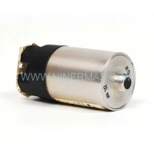
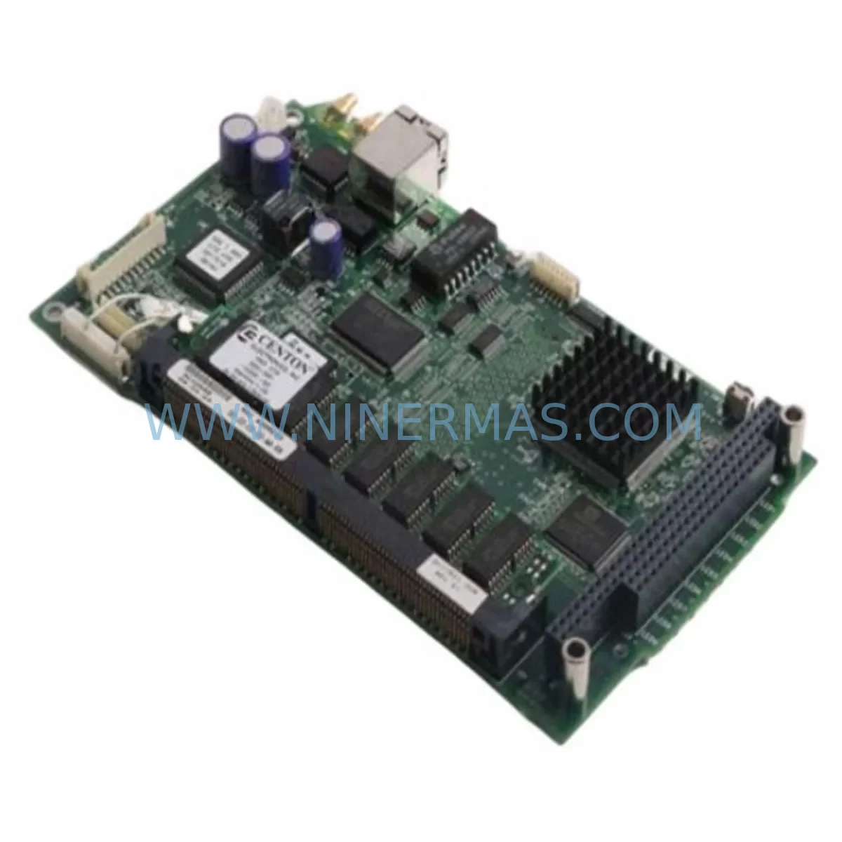
RTF 2017502-001 Retrofit-Compatible PLC Control Module
Verify the part, confirm the platform family, and move straight into quotation with the right commercial details.
RFQ Ready
- SKU2017502-001 2021055-001 2017501-006 2022031-001
- CategoryPLC & Industrial Automation Modules
- BrandRTF
- SupportAvailability, lead time, condition, and shipping coordination
How Buyers Usually Use This Page
- Confirm the exact part number and platform family before sending the quote request.
- Use direct email when quantity, condition, and destination are already defined internally.
- Switch to the broader brand or category archive when you need alternates nearby.
Series Navigation
Move through the most common platform families behind this part.
Product RFQ
Send this part directly for quotation.
Include quantity, required condition, destination country, and target delivery timing. Current reference: RTF 2017502-001 Retrofit-Compatible PLC Control Module with SKU 2017502-001 2021055-001 2017501-006 2022031-001.
RTF 2017502-001 Retrofit-Compatible PLC Control Module: Legacy System Modernization & Smooth Upgrade Path
The RTF 2017502-001 is a ruggedized PLC control module engineered for retrofit compatibility with aging industrial automation platforms. As a direct replacement candidate for discontinued control hardware across harsh-environment applications — including oil & gas processing, power generation, water treatment, and heavy manufacturing — this module addresses the critical challenge of maintaining operational continuity when original equipment manufacturers have ceased production of legacy spare parts.
Cross-reference SKUs 2021055-001, 2017501-006, and 2022031-001 are confirmed compatible variants within the same RTF control platform family, enabling flexible sourcing across different revision levels of the same base architecture. Each unit ships pre-tested and verified against RTF’s original factory acceptance criteria, with a 12-month warranty covering both hardware integrity and functional performance under rated environmental conditions.
Upgrade Compatibility Table
| Parameter | RTF 2017502-001 (This Unit) | Retrofit Notes |
|---|---|---|
| Cross-Reference SKUs | 2021055-001 / 2017501-006 / 2022031-001 | Confirm revision level before installation |
| Module Form Factor | Ruggedized PLC Control Module | Verify backplane slot pitch and card-edge connector type |
| Power Supply Compatibility | Per RTF platform specification | Confirm DC bus voltage and current draw against existing PSU capacity |
| Communication Interface | RTF native backplane bus | Validate protocol compatibility with existing HMI and SCADA links |
| I/O Addressing | Slot-based module addressing | Preserve original module address assignments in PLC program |
| Terminal Wiring | Compatible with legacy RTF terminal block layout | Verify wire gauge, ferrule type, and torque spec before reconnection |
| Installation Space | Standard RTF rack/chassis footprint | Measure available slot clearance; confirm no adjacent module interference |
| Firmware / Program Logic | Retains original ladder logic compatibility | Back up existing program before module swap; verify tag mapping post-swap |
| HMI Screen Compatibility | Maintains existing HMI data point references | Confirm all HMI tags resolve correctly after module replacement |
| Pre-Shipment Testing | Factory acceptance tested | Test report available on request |
| Warranty | 12 Months | Covers hardware defects and functional performance under rated conditions |
Retrofit Planning for Existing Automation Systems
Successful integration of the RTF 2017502-001 into an existing control architecture requires a structured pre-retrofit assessment. Before scheduling a maintenance window, engineering teams should audit the full control cabinet to identify all interdependent components that may be affected by the module swap.
In most RTF-based control systems, the 2017502-001 occupies a central role within a multi-slot chassis or rack assembly. Adjacent modules — such as RTF analog input modules, digital output modules, and communication interface cards — share the same backplane bus and may require re-initialization after the control module is replaced. If the existing rack also houses an RTF power supply module, verify that its output current capacity is sufficient to support the replacement unit, particularly if the new module revision draws slightly different standby or peak current.
Terminal block wiring is a frequent source of commissioning delays during retrofit projects. Before disconnecting any field wiring, photograph or document all terminal assignments, wire labels, and ferrule types. The RTF 2017502-001 uses a terminal layout consistent with the broader RTF control platform, but minor differences between hardware revisions — particularly between the 2017501-006 and 2021055-001 variants — may affect the position of certain signal commons or shield drain points. Always cross-reference the wiring diagram against the specific revision of the replacement module.
For systems that include an RTF communication module or gateway card handling Modbus RTU, PROFIBUS DP, or proprietary RTF serial protocols, confirm that the new control module’s firmware revision is compatible with the existing communication stack. In some legacy installations, the HMI — whether a panel-mounted operator terminal or a PC-based SCADA workstation — communicates directly with the control module via a dedicated serial or Ethernet port. Verify that all HMI data point addresses, tag names, and polling rates remain valid after the module swap.
I/O expansion modules connected downstream of the 2017502-001 — including remote I/O racks, signal isolators, and analog signal conditioners — should be powered down in a controlled sequence before the control module is removed. This prevents spurious output signals from reaching field devices such as control valves, motor starters, or safety interlocks during the transition. A programming cable and laptop loaded with the RTF programming environment should be on-site during commissioning to allow immediate program verification and, if necessary, minor logic adjustments to accommodate any differences between the original and replacement module.
Where the control system includes an RTF redundancy module or hot-standby configuration, the retrofit procedure must account for the switchover logic. Replacing the primary control module without first disabling the redundancy watchdog can trigger an unplanned failover. Coordinate with the site control engineer to temporarily disable automatic switchover, complete the module replacement, verify normal operation, and then re-enable redundancy monitoring.
Downtime Control During System Migration
Minimizing unplanned downtime is the primary operational concern during any PLC control module replacement on a live production system. The RTF 2017502-001 retrofit process is designed to support a structured, low-risk migration approach that protects existing program logic and maintains field control continuity throughout the transition.
Begin by scheduling the module swap during a planned maintenance window — ideally aligned with an existing production shutdown or shift changeover. Before the window opens, complete all preparatory steps offline: obtain the replacement module, verify its revision against the cross-reference list (2021055-001, 2017501-006, 2022031-001), and confirm that a current backup of the PLC program is stored on a secure, accessible medium. Use the RTF programming software to export the full project file, including all program blocks, data tables, I/O configuration, and communication settings.
During the maintenance window, follow a strict sequence: power down the control cabinet in the correct order, remove the failed or end-of-life module, install the RTF 2017502-001, reconnect all terminal wiring per the documented layout, and restore power. Before returning the system to automatic control, perform a manual I/O check to confirm that all digital and analog signals are reading correctly at the controller. Verify communication links to any connected HMI panels, remote I/O stations, and SCADA systems. Only after all signals are confirmed healthy should the system be returned to automatic mode.
If the original module failed unexpectedly and no planned window is available, the RTF 2017502-001’s pre-tested condition and documented compatibility with the RTF platform family allows for an accelerated emergency replacement procedure. Having this module in local inventory — rather than relying on spot-market procurement — is the single most effective strategy for reducing mean time to repair (MTTR) on critical control loops.
Post-replacement, document the installation date, module serial number, firmware revision, and any program changes made during commissioning. This record supports future maintenance planning and provides the baseline data required to initiate a warranty claim if a hardware defect is identified within the 12-month coverage period.
Retrofit Support FAQ
Q1: Is the RTF 2017502-001 a direct drop-in replacement for the 2021055-001 and 2017501-006?
A: These SKUs are cross-reference variants within the same RTF control module family and share the same base architecture. However, minor differences in hardware revision, firmware version, or connector pinout may exist between specific production batches. Always verify the revision level of the replacement unit against your existing system documentation before installation. Our technical team can assist with revision-level compatibility confirmation prior to shipment.
Q2: What commissioning steps are required after installing the RTF 2017502-001?
A: After physical installation and wiring reconnection, restore the PLC program from your backup using the RTF programming environment. Perform a full I/O force test to verify that all digital inputs, digital outputs, and analog channels are responding correctly. Confirm communication links to all connected devices — including HMI panels, communication modules, and any remote I/O racks. Check that all HMI tag references resolve correctly and that no alarm conditions are present before returning the system to automatic control.
Q3: Has this unit been tested before shipment, and what does the 12-month warranty cover?
A: Yes. Every RTF 2017502-001 unit undergoes factory acceptance testing prior to shipment, verifying power-up behavior, I/O channel integrity, communication interface function, and environmental stress performance. The 12-month warranty covers hardware defects and functional failures under rated operating conditions. Warranty claims are supported by our technical team and include options for advance replacement to minimize production downtime.
Q4: Do you maintain stock of the RTF 2017502-001 and related cross-reference modules?
A: Yes. We maintain dedicated inventory of the RTF 2017502-001 and its cross-reference variants (2021055-001, 2017501-006, 2022031-001) to support emergency replacement and planned spare parts programs. Contact our team to confirm current stock levels, lead times, and volume pricing for long-term spare parts agreements.
| Product Series | Other series |
|---|
Catalog Continuation
Alternative parts within PLC & Industrial Automation Modules.
Stay inside the same system family when you need substitutes, adjacent modules, or a broader shortlist for procurement review.
SKU: 14L41-RS0B0-B24R-ST5S00N-R0SU
LENZE 14L41-RS0B0-B24R-ST5S00N-R0SU Retrofit for Legacy Systems
SKU: CI540 3BSE001077R1
ABB CI540 3BSE001077R1 Spare Part for Industrial Maintenance
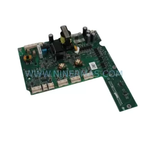
SKU: ZINT-541 3AUA00000658960
ABB ZINT-541 3AUA00000658960 Retrofit-Compatible Inverter Power Module