Original Industrial Spare Part
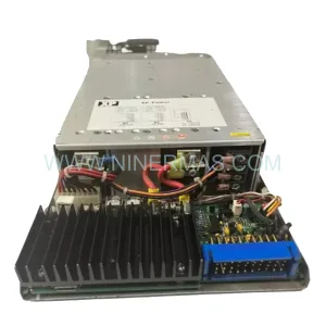
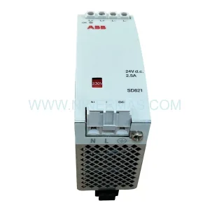
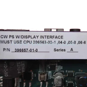
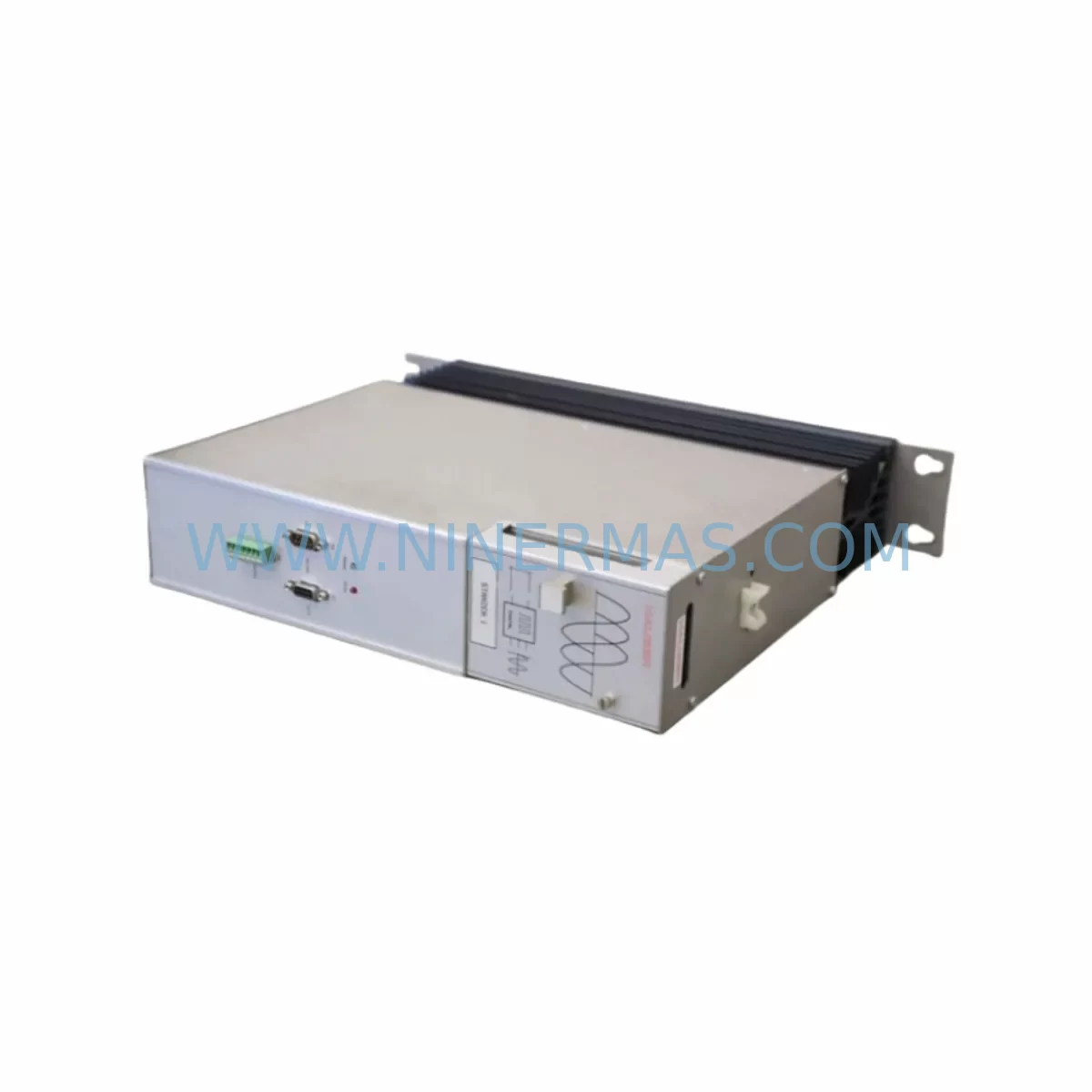
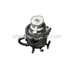
Parker 951-300000 Retrofit Power Supply for Legacy Systems
Verify the part, confirm the platform family, and move straight into quotation with the right commercial details.
RFQ Ready
- SKU951-300000
- CategoryPLC & Industrial Automation Modules
- BrandParker
- SupportAvailability, lead time, condition, and shipping coordination
How Buyers Usually Use This Page
- Confirm the exact part number and platform family before sending the quote request.
- Use direct email when quantity, condition, and destination are already defined internally.
- Switch to the broader brand or category archive when you need alternates nearby.
Series Navigation
Move through the most common platform families behind this part.
Product RFQ
Send this part directly for quotation.
Include quantity, required condition, destination country, and target delivery timing. Current reference: Parker 951-300000 Retrofit Power Supply for Legacy Systems with SKU 951-300000.
Parker 951-300000 Retrofit Power Supply for Legacy Systems
The Parker 951-300000 is a ruggedized power supply module engineered for demanding industrial environments where reliability, voltage stability, and long-term availability are non-negotiable. As legacy Parker 951 Series AC drive platforms approach end-of-life, plant engineers and maintenance teams increasingly rely on the 951-300000 to sustain operational continuity without committing to a full drive replacement. This module delivers regulated DC bus power to the 951 Series drive stack, supporting both single-axis and multi-axis configurations commonly found in legacy motion control cabinets across manufacturing, material handling, and process automation sectors.
For facilities running Parker 951 Series drives alongside companion modules such as the 951-100000 axis module, 951-200000 communications interface, or 951-400000 I/O expansion module, the 951-300000 power supply serves as the backbone of the entire control architecture. Its ruggedized design accommodates wide ambient temperature ranges, vibration-prone environments, and dusty or humid plant floors — conditions that accelerate failure in standard-grade power supplies. When the original 951-300000 fails or degrades, the downstream impact is immediate: axis modules lose regulated power, encoder feedback becomes unreliable, and the entire drive stack may fault out, triggering unplanned downtime.
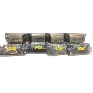
NINERMAS maintains verified stock of the Parker 951-300000 sourced from original Parker Hannifin supply channels, with each unit subject to pre-shipment functional testing. All units are covered by a 12-month warranty from the date of delivery.
Upgrade Compatibility Table
| Parameter | Details |
|---|---|
| SKU / Part Number | 951-300000 |
| Brand / Manufacturer | Parker Hannifin (SSD Drives) |
| Series | Parker 951 Series |
| Module Function | Ruggedized DC Bus Power Supply |
| Compatible Drive Stack | Parker 951 Series multi-axis drive systems |
| Typical Replacement For | Failed or degraded 951-300000 OEM units in legacy installations |
| Backplane / Rack Interface | Parker 951 Series proprietary backplane connector |
| Installation Requirement | Match slot position and backplane pin alignment; verify DC bus voltage rating before energising |
| Communication Compatibility | Compatible with 951 Series internal comms bus; no protocol reconfiguration required for direct replacement |
| Commissioning Note | Verify drive firmware version; re-initialise axis parameters after power supply swap if drive faults persist |
| Warranty | 12 Months from date of delivery |
| Pre-Shipment Testing | Functional output voltage and load regulation test performed on every unit |
| Availability | In stock — global shipping available |
Retrofit Planning for Existing Automation Systems
A successful retrofit of the Parker 951-300000 begins well before the replacement unit arrives on site. Maintenance engineers should start by auditing the full 951 Series drive stack to identify every module drawing power from the existing supply rail. In a typical multi-axis cabinet, this includes one or more 951-100000 axis modules, a 951-200000 serial communications interface card, and potentially a 951-400000 I/O expansion module handling digital and analogue field signals. Each of these modules must be accounted for in the power budget calculation to confirm that the replacement 951-300000 can sustain the aggregate load without thermal derating.
Terminal wiring is a critical checkpoint. The 951-300000 connects to the AC mains input via dedicated terminal blocks on the drive cabinet’s power distribution rail. Before disconnection, photograph or document the existing wiring layout, including PE earth bonding, EMC filter connections, and any upstream circuit breaker or fused disconnect ratings. Mains input phasing and voltage tolerance must be verified against the module’s nameplate rating — mismatched input voltage is a common cause of premature power supply failure in retrofit scenarios.
Backplane seating requires careful attention. The 951-300000 engages the 951 Series backplane through a multi-pin edge connector. Inspect the backplane for bent or corroded pins before inserting the replacement module. If the cabinet has been in service for more than a decade, consider replacing the backplane connector housing as a preventive measure, particularly if the original failure was caused by a power surge or short circuit that may have stressed the connector interface.
Module addressing is handled automatically by the 951 Series backplane in most configurations, but engineers should confirm slot assignments in the drive’s configuration software — typically Parker’s DSE Lite or SSD Drive Setup Environment — before powering up. If the system also includes a Parker AC890 series drive or a Parker Compax3 servo controller sharing the same control cabinet, ensure that the DC bus isolation between drive families is maintained to prevent cross-contamination of fault conditions.
HMI screens connected via a Parker HA501 operator panel or a third-party SCADA terminal should be reviewed for any power supply status alarms or drive health pages that reference the 951-300000 directly. Update alarm descriptors if the replacement unit carries a revised firmware baseline. Communication links running over RS-485 Modbus or Parker’s proprietary SSD serial protocol should be tested end-to-end after the swap, as power supply instability in the original unit may have introduced intermittent communication errors that were previously attributed to the communications module rather than the supply rail.
For installations where the 951-300000 powers a rack that also includes a Parker 890 series regenerative front end or a Parker 590 series DC drive operating in a hybrid legacy topology, confirm that the DC bus voltage levels remain within the specified tolerance band for all connected drives before resuming production. Signal isolators on analogue reference inputs — particularly 4–20 mA speed reference signals — should be re-verified after the power supply replacement, as ground potential shifts during the swap can introduce offset errors in unprotected analogue loops.
Downtime Control During System Migration
Minimising downtime during a Parker 951-300000 replacement requires a structured pre-outage preparation protocol. Begin by uploading a full parameter backup from every 951 Series axis module using Parker’s DSE Lite software or a compatible programming cable. Store the backup file off-machine on a dedicated maintenance laptop or network share. This ensures that if the drive stack requires a full re-initialisation after the power supply swap, axis parameters, ramp profiles, torque limits, and encoder configurations can be restored in minutes rather than hours.
Schedule the replacement during a planned maintenance window rather than responding reactively to a catastrophic failure. A proactive swap on a degrading 951-300000 — identified through elevated output ripple, thermal warnings, or intermittent axis faults — allows the maintenance team to prepare the replacement unit, gather the correct tools, and brief the operations team on the expected outage window. Reactive replacements under production pressure increase the risk of wiring errors, incorrect module seating, and overlooked commissioning steps.
During the physical swap, maintain field control continuity where possible by isolating only the affected drive stack rather than shutting down the entire control panel. If the 951 Series cabinet shares a common control power rail with adjacent PLCs, safety relays, or HMI panels, use temporary 24 VDC bridging supplies to keep those devices energised during the drive cabinet outage. This preserves PLC program execution, safety circuit integrity, and operator visibility throughout the replacement procedure.
After installing the replacement 951-300000, perform a staged power-up sequence: apply control power first, verify that all axis modules enumerate correctly on the backplane, then apply mains power and confirm DC bus voltage before enabling drive outputs. Run a no-load jog test on each axis before reconnecting mechanical loads. Document the commissioning results — including DC bus voltage readings, axis fault logs, and communication link status — as part of the site maintenance record. This documentation supports warranty claims and provides a baseline for future predictive maintenance intervals.
Retrofit Support FAQ
Q1: Is the Parker 951-300000 a direct drop-in replacement for the original OEM unit?
Yes. The 951-300000 is designed as a direct replacement for the original Parker 951 Series power supply module. It uses the same backplane connector, occupies the same rack slot, and operates within the same input voltage and output current specifications as the OEM unit. No mechanical modification or firmware update is required for a standard like-for-like swap, though parameter verification is always recommended after any power supply replacement.
Q2: What commissioning steps are required after installing the replacement module?
After physical installation, verify DC bus output voltage under no-load conditions before enabling axis modules. Confirm that all 951 Series axis modules enumerate correctly on the backplane. Restore axis parameters from a pre-swap backup if the drive stack performed a full reset. Test communication links to the host PLC or SCADA system and run a no-load jog cycle on each axis before resuming production. Document all commissioning readings for the site maintenance record.
Q3: How do I confirm compatibility if my 951 Series cabinet includes additional modules or a mixed drive topology?
Verify the total power draw of all modules connected to the 951-300000 supply rail — including axis modules, I/O expansion modules, and communications interface cards — against the module’s rated output current. For cabinets that include Parker 590 or 890 series drives sharing the same enclosure, confirm DC bus isolation between drive families. Contact NINERMAS with your full cabinet configuration for a compatibility assessment before ordering.
Q4: What warranty and testing does NINERMAS provide with the Parker 951-300000?
Every Parker 951-300000 unit shipped by NINERMAS undergoes pre-shipment functional testing covering output voltage regulation and load response. All units are covered by a 12-month warranty from the date of delivery. Warranty support includes technical assistance for installation and commissioning issues. Units confirmed defective within the warranty period are replaced or refunded subject to inspection. Contact sale@ninermas.com for warranty claims or pre-sales technical enquiries.
| Product Series | Legacy |
|---|
Catalog Continuation
More Parker modules in the catalog.
Use the brand lane to compare nearby part numbers, platform-adjacent modules, and other inquiry-ready listings before sending your final RFQ.
SKU: 016-80686-0 R1E02 2512 A1
Parker 016-80686-0 R1E02 2512 A1 Retrofit Safety Relief Module
SKU: 605-Z-230CE 0190-08538 CDN127-4 114RR-BJ-000-000
Parker 605-Z-230CE-0190 Retrofit DC Drive for Legacy Systems
Catalog Continuation
Alternative parts within PLC & Industrial Automation Modules.
Stay inside the same system family when you need substitutes, adjacent modules, or a broader shortlist for procurement review.