Original Industrial Spare Part
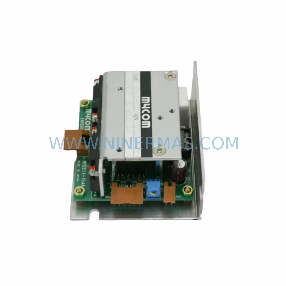
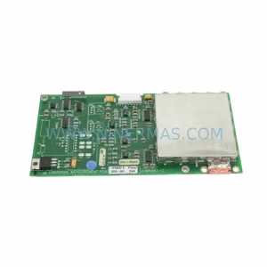
MYCOM IMS500-120AL Retrofit-Compatible DC Driver Module
Verify the part, confirm the platform family, and move straight into quotation with the right commercial details.
RFQ Ready
- SKUIMS500-120AL
- CategoryPLC & Industrial Automation Modules
- BrandMYCOM
- SupportAvailability, lead time, condition, and shipping coordination
How Buyers Usually Use This Page
- Confirm the exact part number and platform family before sending the quote request.
- Use direct email when quantity, condition, and destination are already defined internally.
- Switch to the broader brand or category archive when you need alternates nearby.
Series Navigation
Move through the most common platform families behind this part.
Product RFQ
Send this part directly for quotation.
Include quantity, required condition, destination country, and target delivery timing. Current reference: MYCOM IMS500-120AL Retrofit-Compatible DC Driver Module with SKU IMS500-120AL.
MYCOM IMS500-120AL Retrofit-Compatible DC Driver Module: Legacy System Compatibility and Smooth Upgrade Path
The MYCOM IMS500-120AL is a ruggedized DC driver module engineered for demanding industrial environments and designed as a retrofit-compatible replacement for aging MYCOM IMS-series motion control systems. As legacy stepper motor driver platforms approach end-of-life and original spare parts become increasingly scarce, the IMS500-120AL provides a reliable, drop-in-compatible solution that preserves existing wiring infrastructure, control logic, and mechanical mounting arrangements — minimizing retrofit risk and reducing planned downtime to the shortest possible window.
Industrial facilities operating MYCOM IMS series stepper controllers — including earlier variants such as the IMS400 series and IMS300 series driver boards — frequently encounter obsolescence challenges when sourcing replacement modules. The IMS500-120AL addresses this directly by maintaining electrical compatibility with standard MYCOM driver rack backplanes, accepting the same DC bus voltage range, and supporting equivalent step/direction signal interfaces used across the IMS platform generation. Engineers responsible for legacy motion control cabinet upgrades can integrate the IMS500-120AL without redesigning the control panel layout or rewriting PLC ladder logic, provided that power supply capacity, terminal block assignments, and axis address configurations are verified prior to commissioning.
Upgrade Compatibility Table
| Parameter | IMS500-120AL (This Unit) | Retrofit Notes |
|---|---|---|
| Module Type | DC Stepper Driver Module | Direct replacement for IMS400/IMS300 series driver slots |
| Input Voltage | DC 24V–120V (AL-rated) | Verify existing PSU output capacity before swap; confirm no shared rail overload |
| Step/Direction Interface | Standard 5V TTL / Open Collector | Compatible with MYCOM IMS-series controller pulse outputs; check signal voltage level |
| Backplane / Rack Interface | MYCOM IMS500-series rack slot | Confirm rack generation; IMS300-era racks may require adapter bracket |
| Terminal Block Wiring | Screw-type, standard pitch | Re-use existing motor phase wiring; verify A+/A−/B+/B− polarity before energizing |
| Axis Address Setting | DIP switch configurable | Match original axis address to avoid PLC communication conflicts |
| Communication Protocol | Pulse/Direction (standalone); RS-232/RS-485 optional | If upgrading to RS-485 network, confirm host controller baud rate and protocol version |
| Mounting / Form Factor | DIN rail / panel mount, IMS500 footprint | Fits standard IMS500-series cabinet cutout; no panel modification required |
| Commissioning / Debug | LED status indicators, fault output relay | Use MYCOM IMS programming cable or RS-232 terminal for parameter verification |
| Warranty | 12-Month Warranty — all units pre-shipment tested under load conditions | |
Retrofit Planning for Existing Automation Systems
A successful IMS500-120AL retrofit begins well before the module arrives on site. Maintenance engineers should start by auditing the existing control cabinet to document the current MYCOM IMS driver rack configuration, including the number of occupied axis slots, the DC power supply rail voltage and current capacity, and the routing of motor phase cables to each stepper axis. In multi-axis systems, it is common to find a shared DC bus feeding several driver slots simultaneously — replacing one IMS400-series module with the IMS500-120AL requires confirming that the existing power supply module (such as a MYCOM PSU-series or equivalent third-party 24V/48V DC supply) can sustain the combined inrush and continuous current demand without triggering overcurrent protection.
Terminal block wiring is a critical checkpoint. The IMS500-120AL uses a standard screw-terminal interface for motor phase connections (A+, A−, B+, B−) and control signal inputs (STEP, DIR, ENABLE, ALARM). Before disconnecting the legacy module, technicians should photograph or transcribe the existing wiring layout and cross-reference it against the IMS500-120AL terminal assignment diagram. In many legacy MYCOM installations, the motor cables are labeled by axis number rather than by signal name, making it essential to verify polarity before re-energizing the drive to avoid motor phase reversal or winding damage.
For systems where the host PLC — such as a Mitsubishi MELSEC Q-series, Omron CJ-series, or Siemens S7-300 — communicates with the MYCOM driver rack via a dedicated motion control interface card or high-speed pulse output module, the engineer must confirm that the step frequency range and pulse duty cycle supported by the IMS500-120AL match the output specifications of the existing controller. In applications where the original system used an RS-232 serial link for parameter upload and monitoring, the same MYCOM IMS programming cable and terminal software can typically be reused with the IMS500-120AL, avoiding the need to source new configuration tools.
Where the retrofit scope extends beyond a single driver module — for example, when upgrading an entire motion control cabinet that also includes a MYCOM IMS-series indexer controller, a signal isolation board for encoder feedback, or a dedicated HMI panel running legacy MYCOM monitoring screens — the IMS500-120AL can be integrated as part of a phased upgrade. In phase one, the driver module is replaced while retaining the existing indexer and HMI; in phase two, the indexer and communication interface are upgraded to a current-generation motion controller, with the IMS500-120AL remaining in service as the axis drive. This staged approach allows production to resume after a short commissioning window rather than requiring a full system shutdown for a complete platform migration.
I/O expansion requirements should also be assessed during retrofit planning. If the existing system relies on discrete I/O signals routed through a MYCOM IMS backplane — such as home sensor inputs, limit switch signals, or alarm relay outputs — the engineer should verify that these signal paths are preserved in the new wiring layout and that any signal conditioning or isolation modules in the cabinet remain compatible with the IMS500-120AL’s input voltage thresholds.
Downtime Control During System Migration
Minimizing unplanned downtime is the primary operational concern when replacing a DC driver module in a live production environment. The IMS500-120AL retrofit process is designed to support a controlled, single-shift changeover when the site team follows a structured pre-commissioning checklist. Before the maintenance window begins, the replacement module should be bench-tested using a known-good stepper motor and a bench power supply to verify that the unit responds correctly to step/direction inputs, that the fault relay operates as expected, and that the current limit and decay mode settings are configured to match the original axis parameters.
During the changeover, the original PLC program and HMI screen configuration should be backed up to a laptop or USB drive before any hardware is disconnected. In systems where the MYCOM driver communicates axis status back to the PLC via a serial link or discrete alarm output, the engineer should note the current alarm state and confirm that the replacement module’s alarm output wiring matches the PLC input card’s signal expectations. If the system uses a MYCOM IMS-series multi-axis controller that stores axis parameters internally, those parameters should be exported using the MYCOM configuration software before the old module is removed, so they can be uploaded to the IMS500-120AL immediately after installation.
Once the IMS500-120AL is installed and wired, the commissioning sequence should begin at reduced speed and current to verify correct motor rotation direction, home sensor detection, and limit switch response before returning the axis to full production speed. The module’s LED status indicators provide real-time feedback on power, enable state, and fault conditions, allowing the technician to identify and resolve any wiring or configuration issues without requiring an oscilloscope or additional diagnostic equipment. With proper pre-commissioning preparation, most single-axis IMS500-120AL replacements can be completed within a two-to-four hour maintenance window, including functional testing and sign-off.
Retrofit Support FAQ
Q1: Is the MYCOM IMS500-120AL a direct drop-in replacement for IMS400-series and IMS300-series driver modules?
In most cases, yes — the IMS500-120AL is designed to be electrically and mechanically compatible with the IMS500-series rack slot and shares the same terminal block pinout as the IMS400 series. For IMS300-era installations, a rack adapter bracket may be required due to differences in the backplane connector generation. We recommend confirming the rack model number before ordering to ensure full mechanical compatibility.
Q2: What pre-shipment testing is performed on the IMS500-120AL before dispatch?
Every IMS500-120AL unit supplied by NINERMAS undergoes a full functional test under load conditions prior to shipment. This includes DC bus power-up verification, step/direction signal response testing at rated frequency, current limit validation, and fault relay operation confirmation. A test report is available upon request. All units are covered by a 12-month warranty from the date of shipment.
Q3: Can the IMS500-120AL be configured for RS-485 network communication to replace a legacy RS-232 linked axis?
The IMS500-120AL supports optional RS-485 communication in addition to the standard pulse/direction interface. If the existing system uses RS-232 for parameter monitoring only (not for real-time motion commands), the transition to RS-485 can be made during the retrofit without changes to the PLC program, provided the host controller supports RS-485 and the baud rate and protocol version are matched. For systems where RS-232 is used for real-time indexer communication, a protocol migration plan should be developed before the changeover.
Q4: What is the lead time and stock availability for the IMS500-120AL?
NINERMAS maintains stock of the IMS500-120AL to support urgent maintenance and planned retrofit projects. Standard lead time for in-stock units is 3–7 business days for international shipment. For large-quantity orders or long-term spare parts programs, we offer reserved stock arrangements with agreed delivery schedules. Contact our team at sale@ninermas.com or +0086 187 5021 5667 to confirm current availability and arrange a supply agreement.
| Product Series | Other series |
|---|
Catalog Continuation
Alternative parts within PLC & Industrial Automation Modules.
Stay inside the same system family when you need substitutes, adjacent modules, or a broader shortlist for procurement review.
SKU: 16-167627-00 8122 410 05002, 4022.470.78191 8122 410 55702 16-273491-00
Novellus 16-167627-00 Service-Ready Industrial Spare Part
SKU: 2305451-C DT2000 0626 P2, OLE36-10632-02
Advanced Energy 2305451-C Service-Ready Industrial Spare Part