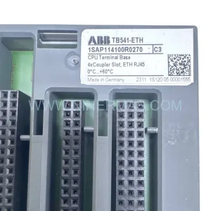
Original Industrial Spare Part
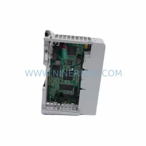
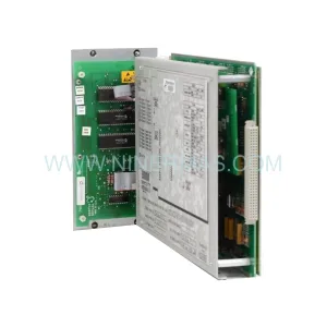
LTi LSC-192-2-20-560-P6B0R1PM0 Retrofit Servo Drive for Legacy Systems
Verify the part, confirm the platform family, and move straight into quotation with the right commercial details.
RFQ Ready
- SKULSC-192-2-20-560-P6B0R1PM0
- CategoryPLC & Industrial Automation Modules
- BrandLTi Drives
- SupportAvailability, lead time, condition, and shipping coordination
How Buyers Usually Use This Page
- Confirm the exact part number and platform family before sending the quote request.
- Use direct email when quantity, condition, and destination are already defined internally.
- Switch to the broader brand or category archive when you need alternates nearby.
Series Navigation
Move through the most common platform families behind this part.
Product RFQ
Send this part directly for quotation.
Include quantity, required condition, destination country, and target delivery timing. Current reference: LTi LSC-192-2-20-560-P6B0R1PM0 Retrofit Servo Drive for Legacy Systems with SKU LSC-192-2-20-560-P6B0R1PM0.
LTi LSC-192-2-20-560-P6B0R1PM0 Retrofit Servo Drive for Legacy Systems
The LTi LSC-192-2-20-560-P6B0R1PM0 is a compact, high-performance servo drive from LTi Drives (formerly Lust Antriebstechnik), designed for precise motion control in demanding industrial environments. As the LSC-192 series approaches end-of-life and original spare parts become increasingly scarce, plant engineers and maintenance teams face mounting pressure to source verified replacement units or plan a structured retrofit path that preserves existing control logic, minimises downtime, and protects capital investment in legacy automation infrastructure.
This unit operates within the LSC-192 platform, a servo controller family widely deployed across packaging lines, textile machinery, printing presses, material handling conveyors, and CNC auxiliary axes throughout Europe and Asia. The P6B0R1PM0 option code indicates a specific combination of feedback interface, communication protocol, and I/O configuration that must be carefully matched during any replacement or upgrade project. Whether you are sourcing a direct drop-in spare or planning a phased migration to a current-generation drive platform, understanding the electrical and mechanical interface requirements of this module is the critical first step.
Upgrade Compatibility Table
| Parameter | LSC-192-2-20-560-P6B0R1PM0 (Original) | Retrofit / Replacement Notes |
|---|---|---|
| DC Bus Voltage | 560 V DC | Verify DC bus rail from existing power supply module before installation |
| Continuous Output Current | 2 A (nominal) | Confirm motor nameplate current; derate if ambient temperature exceeds 40 °C |
| Feedback Interface | Resolver / Encoder (P6 option) | Match encoder cable pinout; re-parameterise resolver offset after swap |
| Communication Protocol | CANopen (B0 option) | Verify node address, baud rate, and PDO mapping in existing PLC program |
| Control Interface | Analogue ±10 V / Digital I/O | Check terminal block wiring diagram; I/O polarity may differ on replacement units |
| Mounting Format | Panel-mount, DIN-rail compatible | Confirm cabinet depth and clearance for airflow; minimum 50 mm side clearance |
| Firmware Compatibility | LSC-192 firmware family | Upload original parameter file via LTi DriveManager before commissioning |
| Warranty | — | 12-Month Warranty included with every unit supplied by NINERMAS |
Retrofit Planning for Existing Automation Systems
A successful retrofit of the LSC-192-2-20-560-P6B0R1PM0 begins well before the replacement unit arrives on site. Maintenance engineers should first audit the existing control cabinet to document every interface the drive shares with surrounding equipment. In a typical LSC-192 installation, the servo drive sits on a shared DC bus alongside one or more additional LSC-192 axis modules — for example, an LSC-192-1-20-560 single-axis unit driving a feed roller or an LSC-192-4-20-560 higher-current module controlling a main spindle. The DC bus capacitor bank and the associated mains filter and regenerative braking resistor must be inspected for wear before the new drive is energised.
On the communication side, the CANopen network linking the LSC-192-2-20-560-P6B0R1PM0 to the host PLC — often a Siemens S7-300 or a Beckhoff CX series controller — must be verified for correct termination resistance (120 Ω at each end of the bus) and stable baud rate negotiation. If the site uses a CANopen-to-PROFIBUS gateway or a DeviceNet bridge module to connect the drive network to a higher-level SCADA system, those gateway configurations must be exported and preserved before any hardware is disturbed.
The feedback wiring between the LSC-192 drive and the attached servo motor deserves particular attention. Resolver-based motors require a precise offset calibration stored in the drive’s non-volatile memory. Before removing the original drive, use LTi DriveManager software connected via the RS-232 or USB programming cable to export the full parameter set, including the resolver offset angle, speed controller gains, position window, and fault response configuration. This parameter file becomes the baseline for commissioning the replacement unit.
For sites where the LSC-192 drives share a cabinet with LTi power supply modules such as the PSU-192 series or with an LTi CDA-32 or CDB-01 regenerative supply unit, the inrush current sequencing on power-up must be re-validated after the drive swap. Incorrect sequencing can trip the main contactor or damage the DC bus capacitors. Similarly, if the control system includes an LTi EPM-T110 expansion I/O module or a dedicated signal isolator board for analogue reference signals, the wiring to those peripheral modules must be checked against the original schematic before the cabinet is re-energised.
HMI panels connected to the drive — whether a standalone operator panel mounted on the cabinet door or a remote touch-screen running a SCADA visualisation — may display drive status variables mapped directly from the CANopen object dictionary. After replacing the drive, verify that all mapped process data objects (PDOs) and service data objects (SDOs) respond correctly and that alarm codes displayed on the HMI match the new drive’s fault list. Update the HMI project file if the replacement unit uses a revised object dictionary layout.
Downtime Control During System Migration
Minimising production downtime during an LSC-192-2-20-560-P6B0R1PM0 replacement requires a structured pre-commissioning workflow. Begin by preparing the replacement drive on a bench test rig before the scheduled maintenance window. Load the exported parameter file, set the CANopen node address to match the original, and perform a no-load motor run to verify speed loop stability and encoder signal integrity. This bench validation step typically takes two to four hours and eliminates the most common commissioning failures before the drive reaches the production floor.
During the actual cabinet swap, follow a lock-out/tag-out procedure and discharge the DC bus capacitors fully — allow at least five minutes after mains isolation before touching any bus bar. Replace the drive module, reconnect the motor feedback cable and power terminals using the original wiring diagram, and restore the CANopen network termination. On power-up, monitor the bus voltage ramp and confirm that the drive reaches the ready state without fault codes before releasing control to the PLC.
If the original drive cannot be removed cleanly — for example, because the cabinet layout has changed or the terminal block positions differ — a short-term parallel operation strategy may be used: the replacement drive is wired in shadow mode alongside the original, parameters are validated under live conditions, and the final cutover is executed during a planned micro-stoppage of less than 15 minutes. This approach is particularly effective on continuous-process lines where even a brief unplanned stop carries significant cost.
NINERMAS supplies each LSC-192-2-20-560-P6B0R1PM0 unit with a pre-shipment functional test report confirming DC bus charging, output stage switching, and communication interface operation. This documentation supports your internal quality records and accelerates site acceptance testing.
Retrofit Support FAQ
Q1: Is the LSC-192-2-20-560-P6B0R1PM0 a direct drop-in replacement for the original LTi unit?
Yes. NINERMAS supplies original or fully equivalent units that match the mechanical footprint, terminal layout, and firmware compatibility of the factory-original LSC-192-2-20-560-P6B0R1PM0. The option code P6B0R1PM0 is verified against the original build specification before shipment.
Q2: Can I reuse my existing motor feedback cable and CANopen wiring?
In most cases, yes. The resolver/encoder connector pinout and the CANopen RJ45 or D-sub interface are preserved across the LSC-192 production run. However, we recommend verifying cable continuity and shield integrity before reconnection, particularly on installations older than five years.
Q3: What commissioning tools are required after installation?
LTi DriveManager software (Windows-compatible) connected via the drive’s RS-232 service port or USB adapter is required to load the parameter file and perform the resolver offset calibration. NINERMAS can supply a pre-loaded parameter file if you provide your original drive’s parameter export or nameplate data.
Q4: What warranty and stock availability does NINERMAS offer?
Every LSC-192-2-20-560-P6B0R1PM0 unit supplied by NINERMAS carries a 12-month warranty covering manufacturing defects and functional performance. We maintain dedicated stock of LSC-192 series drives to support urgent breakdown requirements, with same-day dispatch available for in-stock units. Contact our technical sales team for lead time confirmation and volume pricing.
| Product Series | Legacy |
|---|
Catalog Continuation
Alternative parts within PLC & Industrial Automation Modules.
Stay inside the same system family when you need substitutes, adjacent modules, or a broader shortlist for procurement review.
SKU: 16-167627-00 8122 410 05002, 4022.470.78191 8122 410 55702 16-273491-00
Novellus 16-167627-00 Service-Ready Industrial Spare Part
SKU: 2305451-C DT2000 0626 P2, OLE36-10632-02
Advanced Energy 2305451-C Service-Ready Industrial Spare Part